Description – Micro Technic PV-1800 User Manual
Page 4
Users Manual & Installation Guide
PV- 1800: Power supply module with GSM MODEM
Page 4 / 19
Description
The PV-1800, the fully equipped model, offers the following features:
• a PC/104 20W power supply +5V, 4A.
• a dual band GSM/GPRS modem (Sony Ericsson GM47)
• 8 isolated analogue inputs, 12 bit
• 8 digital inputs, opto-isolated
• 7 digital outputs, opto-isolated
• one RS232 serial port
• non-isolated simple I/O’s.
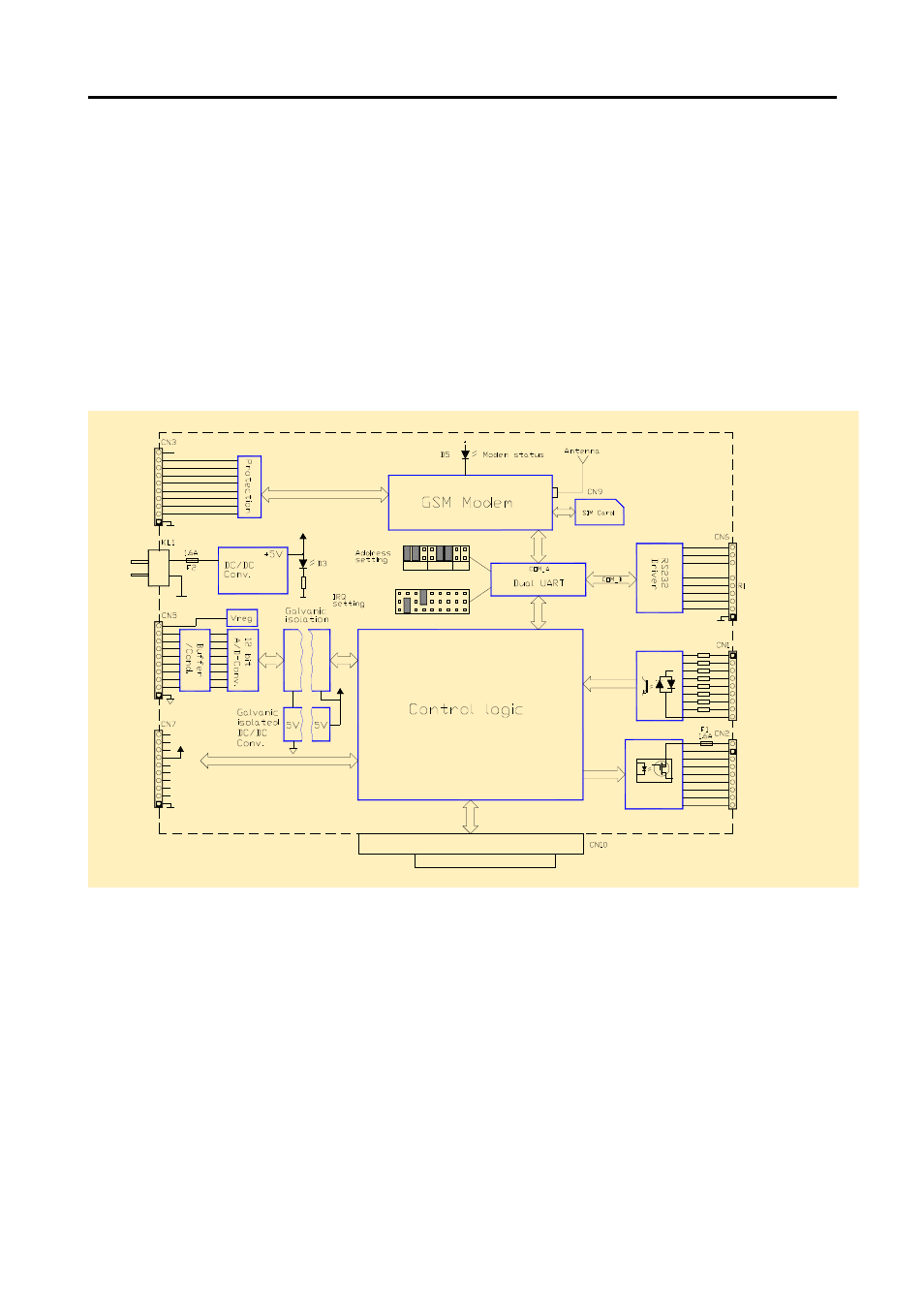
Block diagram
! "
# $
%
!
&'
(
&
)
$
&'
(
)
$
%*&$
+
,-
,-#
.
%-
%-#
'$
*
/
'
&
)
$
%
0
1
2
(
&
$ /
(
3
3
3
3
1
!
.
+
+
.
.
+
.
+
.
+
1! !4
5
5
1! $* $
1! $* $
6&78
5
5
.
+
3 9
7
7:&
*/5
*7 ; $(
. 2 ( <
The PV-1800 has an onboard DC/DC converter that converts the incoming mains (+8-35V DC) to
+5V. This power supply delivers +5V, up to 4A, to the PV-1800 and to the PC/104 bus. A mains
fuse F2 (1.6A) is placed on the rear side of the PCB, near KL1. In PV-1800A versions, where the
DC/DC-converter is omitted, the module receives its power from the PC/104 bus.
The GSM modem is placed on the top side of the PCB while the SIM card connector is placed on
the rear side. The locking mechanism is indicated on the top of the SIM card holder. The connector
for the antenna is placed on the GSM modem itself. The base address of the PV-1800 registers and
COM ports, and IRQs for the modem and the COM port on CN6, are set by two jumper blocks.
The analogue section (PV-1800 only) is available in different configurations including pure voltage
inputs (0-2.5V, 0-5V and 0-10V), pure current inputs (0-20mA) and with mixed inputs (0-2.5V and
0-20mA). The configuration must be decided when ordering – see section ordering codes.
The digital I/O section is found on all models except PV-1830 versions.