Micro Technic PV-1800 User Manual
Page 10
Users Manual & Installation Guide
PV- 1800: Power supply module with GSM MODEM
Page 10 / 19
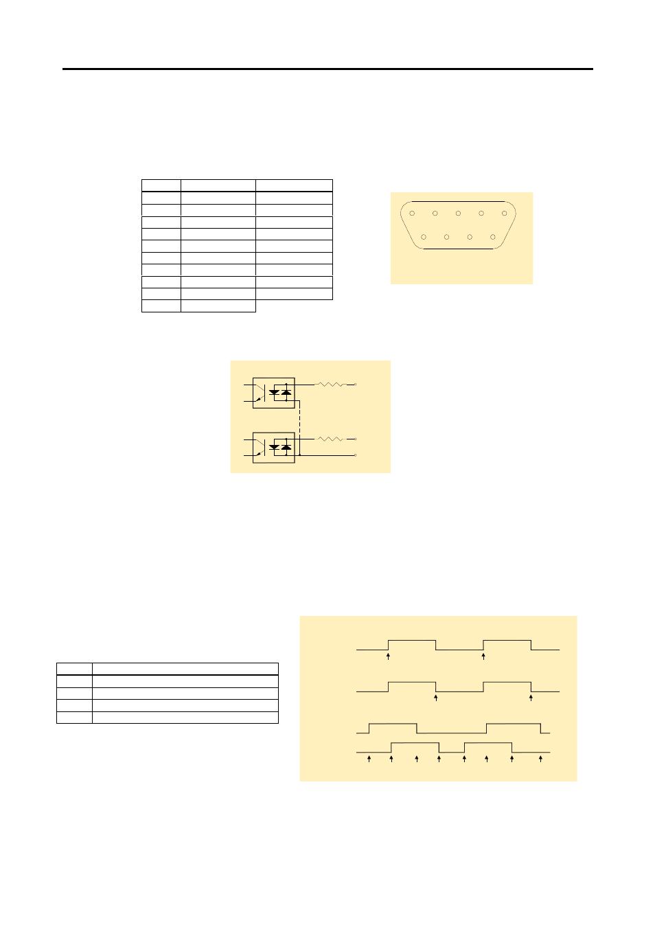
Digital inputs (CN 1)
The PV1800 has 8 isolated digital inputs connected to a 10-pin box header (CN1). All the inputs
have ac-couplers with a common ground reference. Because of the ac-couplers, the inputs can be
activated with positive as well as negative input voltages. The table shows the connector layout:
The input circuitry looks like this:
Counter inputs
The PV-1800 has a 16-bit counter. Besides acting as normal digital inputs, input #0 and #1 can also
be used as counter inputs.
• Input #0: counter input for the 16-bit counter.
• Input #0 together with input #1: counter inputs for a 16-bit quadrature counter.
The counter function can be software programmed to be in one of four modes.
The counter modes are shown here:
The software interface is explained in section PV-1800 register interface.
Pin no Name
Pin no CDB-9F
1
Digital input #0
1
2
Digital input #1
6
3
Digital input #2
2
4
Digital input #3
7
5
Digital input #4
3
6
Digital input #5
8
7
Digital input #6
4
8
Digital input #7
9
9
GND
5
10
NC
Mode Function
0
Disabled
1
Increment on rising edges on DI #0
2
Increment on falling edges on DI #0
3
DI #0 and DI #1 act as a quadrature counter
<
<
-
-
&') $
&&
=
0' $
A
B
)
)
&'
'*&
=
0' $A
B
)
)
, *0*
7
&'A
B
B
)
)
)
)
0 6
0 6
0 6
0 6
.
+
1#+ @5
=&6