Micro Technic PV-1800 User Manual
Page 12
Users Manual & Installation Guide
PV- 1800: Power supply module with GSM MODEM
Page 12 / 19
UPS signals (CN7)
The PV-1800 has signals that, combined with external circuitry, can be used to implement a UPS
function. There is an input for turning off the 20W power supply (SWITCHER_OFF), two status
inputs (UPS_STATUS1 and UPS_STATUS2), and an output (UPS_PWROFF) that can tell the
external circuitry to turn off power after a programmable delay.
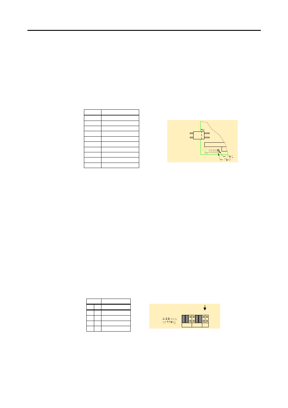
Connector layout:
* = do not connect, for internal factory use.
PV-1800 register interface
The PV-1800 has three blocks of I/O ports: the modem UART, the external RS232
UART and the internal registers. The UARTs are 16C550 compatible and use
eight I/O ports each.
The base addresses of the modem UART and external RS232 UART are configured
on configuration jumper 1,2,3 and 4,5,6 respectively, see the table printed
on the board. The IRQ of both UARTs are configured on the IRQ jumpers. You
cannot use the same IRQ for both UARTs.
Base address
Configuration jumper 7, 8 configure the base address of the sixteen internal
registers. This table is also printed on the board.
ST1
Base address
7 8 Registers
0 0 200h
0 1 220h
1 0 300h
1 1 320h
Pin no Name
1
GND
2
*
3
*
4
*
5
*
6
UPS_PWROFF
7
+5V
8
UPS_STATUS2
9
UPS_STATUS1
10
SWITCHER_OFF
.
%-
%-# '
$