Cabling, Field wiring and signal termination, Field wiring and – Measurement Specialties PCI-DIO24 User Manual
Page 11: Signal termination, Sect, E 11
PCI-DIO24 User's Guide
Installing the PCI-DIO24
11
Information on signal connections
General information regarding signal connection and configuration is available in the Guide to Signal
Connections. This document is available on our web sit
Cabling
20
1
37
19
20
1
37
19
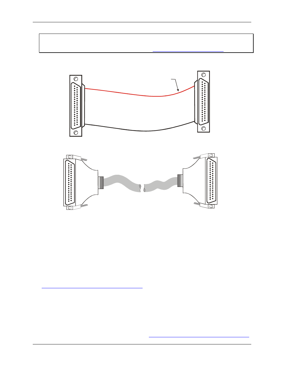
The red stripe
identifies pin # 1
Figure 2. C37FF-x cable
20
1
37
19
20
1
37
19
Figure 3. C37FFS-x cable
Field wiring and signal termination
You can connect the PCI-DIO24 to the following termination boards using the C37FF-x or C37FFS-x cable:
SCB-37 — 37-conductor, shielded signal connection/screw terminal box that provides two independent 37-
pin connections.
CIO-MINI37 — 4 x 4, 37-pin screw terminal board.
CIO-MINI37-VERT
— 37-pin screw terminal accessory with vertical 37-pin male D connector.
CIO-SPADE50
— 16" X 4" termination panel which mates with both 37-pin and 50-pin connectors.
Details on these products are available on our web site at
The following relay racks and accessory boards can be used with the PCI-DIO24:
SSR-RACK24 — 24-position solid state relay rack..
SSR-RACK08 — Eight-channel solid state relay rack.
CIO-ERB08 — Eight-channel electromechanical relay accessory for digital I/O boards.
CIO-SERB08 — Eight Form C and ten socketed relay accessory for digital I/O boards.
CIO-ERB24 — 24-channel electromechanical relay accessory for digital I/O boards.
Details on these products are available on our web sit