MITSUBISHI ELECTRIC VS-60609 User Manual
Page 35
MODELS: VS-45609 / VS-50609 / VS-55609 / VS-60609 / VS-60719 / VS-70709
Page 35
MODELS: VS-45609 / VS-50609 / VS-55609 / VS-60609 / VS-60719 / VS-70709
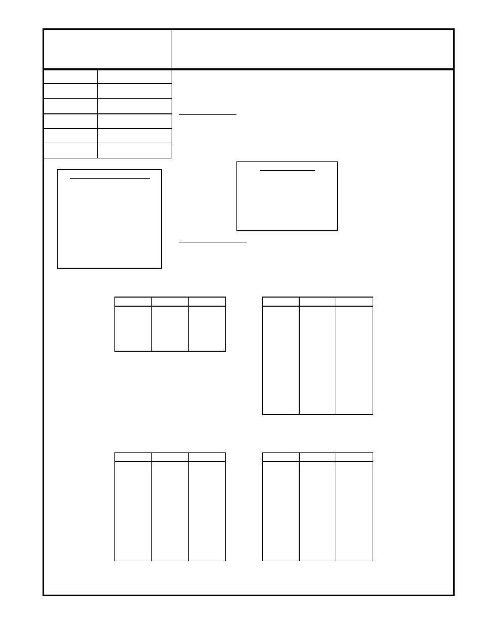
Purpose:
Measuring
Instrument
Test Point
Measuring
Range
Input Signal
Ext. Trigger
Input Terminal
Symptom:
[Defl/Conv Circuits]
-----
-----
------
-----
NTSC RF or Video
Video or RF Input
To preset data values controlling raster geometry.
Raster Distortion
Note:
This procedure us usually only necessary if:
• An E2PROM is replaced in the Control or Convergence circuits.
• E2RESET or Convergence Reset has been activated.
Deflection Circuit
1. Supply NTSC Video signal to the Video or RF Input.
2. Select the NTSC signal as the source (Input button).
3. Enter the Service Mode, VCJ Function.
4. Insure all data values correspond to those in the VCJ Table shown in
Table 1.
5. Save the data and exit the Service Mode.
Convergence Circuit
1. Enter the Convergence Coarse Mode.
2. Set the data in Red, Green and Blue Coarse Convergence Functions to the
data values given in
Tables 2, 3 and 4.
3. Exit the Convergence Mode.
15. Geometry Preset
SERVICE MODE
Activate …….. MENU-0-1-5-7
Function …...………..AUDIO
Item No. ……….…….VIDEO
Adjust Data ….…….ADJUST
Save Data …. ………ENTER
Exit …………..MENU (twice)
CONVERGENCE MODE
Activate ……..MENU-0-1-5-9
Misc. ……………….……"6"
Coarse………………..…."5"
Fine ……………………..."4"
Color (R,G B or DF)...AUDIO
Item No………….…..VIDEO
Adjust/Move……….ADJUST
Cursor Toggle….…..ENTER
Save & Exit…..MENU (twice)
VCJ Function
CONV GREEN
Item
Abbr.
Data
Item
Abbr.
Data
2
VHGT
31
1
HSTA*
0
3
SCOR
7
2
VSTA*
0
4
VLIN
7
3
SKEW
0
51
VPOS
31
4
TILT
0
55
HPOS
34
5
HWID
30
6
HLIN
0
7
SPCC
-125
8
HKEY
30
9
TBPC
-230
10
VKEY
-10
11
VWID
0
12
VLIN
0
* Data should not exceed ±100
CONV RED
CONV BLUE
Item
Abbr.
Data
Item
Abbr.
Data
1
HSTA*
100
1
HSTA*
-100
2
VSTA*
0
2
VSTA*
0
3
SKEW
0
3
SKEW
0
4
TILT
0
4
TILT
0
5
HLIN
-270
5
HLIN
280
6
HWID
-60
6
HWID
-50
7
VKEY
-170
7
VKEY
150
8
VWID
0
8
VWID
0
9
VLIN
0
9
VLIN
0
10
TPBC
0
10
TPBC
0
11
SDBW
80
11
SDBW
-70
* Data should not exceed ±100
* Data should not exceed ±100
Table 1
Table 2
Table 3
Table 4