MITSUBISHI ELECTRIC VS-60609 User Manual
Page 31
MODELS: VS-45609 / VS-50609 / VS-55609 / VS-60609 / VS-60719 / VS-70709
Page 31
Purpose:
Measuring
Instrument
Test Point
Measuring
Range
Input Signal
Ext. Trigger
Input Terminal
Symptom:
Purpose:
Measuring
Instrument
Test Point
Measuring
Range
Input Signal
Ext. Trigger
Input Terminal
Symptom:
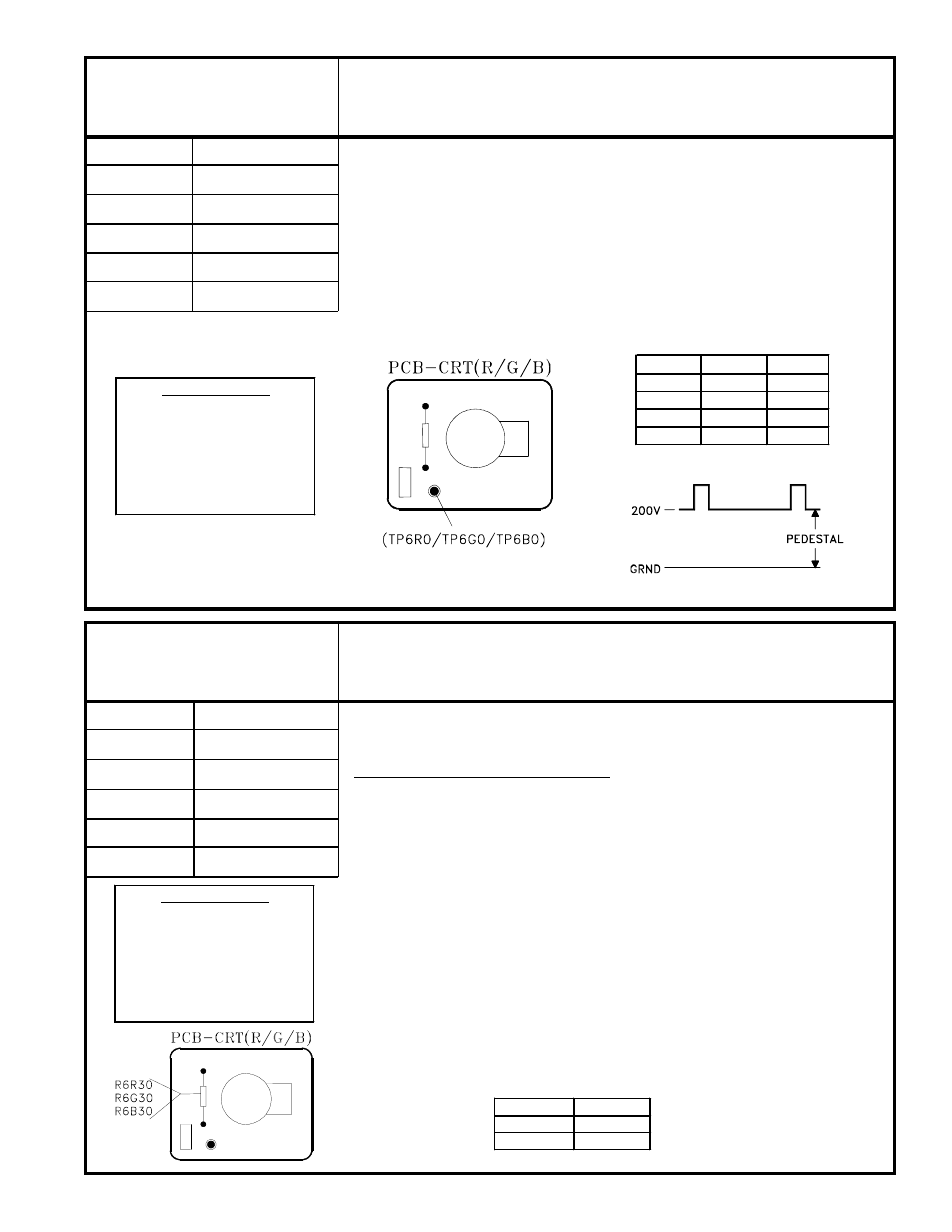
[CRT Circuit]
Oscilloscope
TP6R, TP6G, TP6B
------
50V per division/ 2 msec
None
Video Input
To set the cutoff point for all three CRTs.
Monchrome has a color tint, or incorrect brightness.
1. Select an External Input with no signal.
2. Enter the Service Mode, VCJ Function.
3. Set the data to the values given for the Items listed in the Table.
4. Connect the oscilloscope to TP6R.
5. Adjust the Red SCREEN VR so the black level is 200V, as shown below, or to
206 ±1VDC using a DC Voltmeter.
6. Repeat Steps 4 and 5 to set the Blue and Green SCREEN VRs, using TP6G
and TP6B.
Note:
The White Balance Adjustment must be performed after Cutoff Adjustment.
7. CRT Cutoff
[CRT Circuit]
DC Meter
R6G30, R6B30
------
-------
Full White Raster
Video Input
To set the CRTs white level
Monchrome has a color tint.
Note:
This adjustment must be performed after the CRT Cutoff and Focus
Adjustments.
High Color Temperature White Balance
1. Supply a Full White Raster signal to the Video Input.
2. Enter the Service Mode, VCJ Function.
3. Adjust Items “11 RDRH” and “13 BDRH” for optimum white at the center of the
screen.
Note:
If the Cutoff level changes during the adjustment, use Items “8 CTRH”
and “10 CTBH” to touch up the Cutoff level. Then readjust “RDRH” and
“BDRH”.
4. Save data and exit the Service Mode.
5. Use a DC Current Meter to measure each CRT’s current.
• The meters internal resistance must be less than 30 Ohms.
• Lead length must be less than 30 CM.
6. Connect the meter, in sequence, across each of the following resistors to read
the current for that respective CRT.
• Green CRT ... across R6G30
• Blue CRT ...... across R6B30
7. The Green and Blue CRT current must not exceed the values given in Table 1.
8. White Balance
(High Color Temperature)
Maximun CRT Current
CRT
CURRENT
Green
580 ua
Blue
530 ua
Table 1
SERVICE MODE
Activate …….. MENU-0-1-5-7
Function …...………..AUDIO
Item No. ……….…….VIDEO
Adjust Data ….…….ADJUST
Save Data …. ………ENTER
Exit …………..MENU (twice)
SERVICE MODE
Activate …….. MENU-0-1-5-7
Function …...………..AUDIO
Item No. ……….…….VIDEO
Adjust Data ….…….ADJUST
Save Data …. ………ENTER
Exit …………..MENU (twice)
VCJ Function
ITEM
ABBR.
DATA
7
BRTH
31
8
CTRH
7
9
CTGH
10
10
CTBH
7