4. installing wire guide extension, 5. equipment connection diagram – Miller Electric SS-75S12 User Manual
Page 15
OM-230 298 Page 11
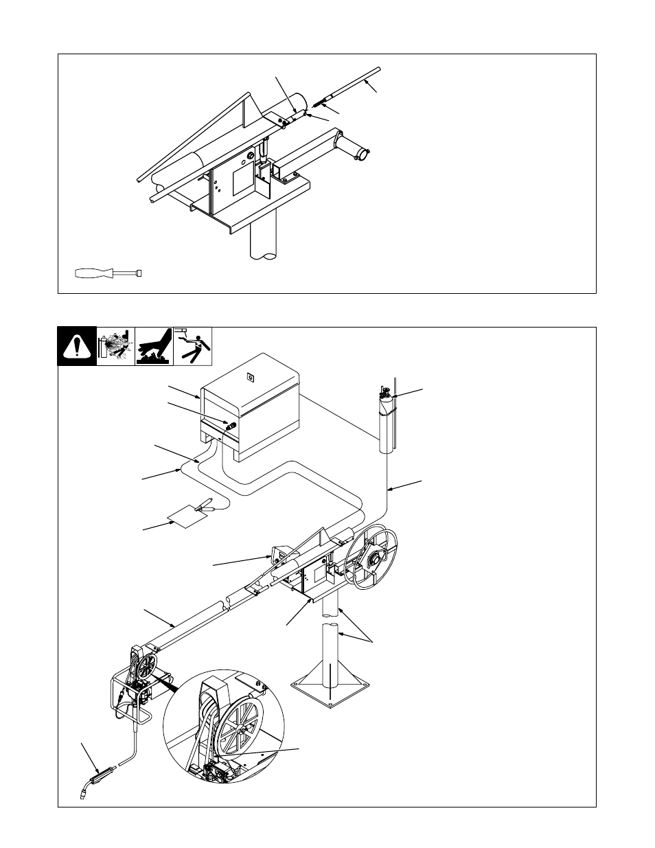
4-4. Installing Wire Guide Extension
ST-152 323
1
Wire Guide Fitting
2
Bolt
3
Monocoil Liner
4
Wire Guide Extension
Tighten bolt to secure liner in wire
guide fitting. Do not overtighten bolt
and crush liner.
1
2
3
4
3/8 in
Tools Needed:
804 726-A
Y Turn Off wire feeder and
welding power source. Stop
engine on welding
generator.
Y Use only with CC/CV DC
Power Sources.
1
Constant Current (CC) or
Constant Voltage (CV)
Welding Power Supply
2
Remote 14 Connection
3
Weld Cable To Feeder
4
Ground Cable To Workpiece
Weld cable and ground cable con-
nections to power source (DCEN/
DCEP) are dependant on wire type.
5
Workpiece
6
Weld Control
7
Boom
8
Gun
9
Trigger Connection
10 Swivel
11 Pipe Post And Base
12 Gas Hose
13 Gas Supply And Regulator
(Customer Supplied)
.
Shielding gas pressure not to
exceed 100 PSI (689 kPa).
4-5. Equipment Connection Diagram
1
4
5
6
7
8
10
11
12
13
2
3
9