Block diagram, Io1500r, Page 6 of 8 – Motorola iO1500R User Manual
Page 6
Page 6 of 8
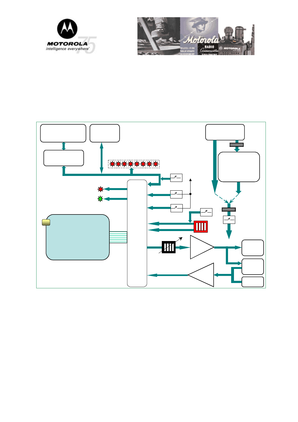
Block Diagram
The following is the block diagram of the evaluation board:
The interconnections of all major components, switches, connectors, LED’s and other
important parts of the board are presented here.
J1
30 Pin
ZIF
Connector
J120
RS232 Connector
Level Shifter
U123
J121
USB
Connector
Data Pins 24-30
Mic
Amplifier
J122
Mic In
J80
Headset
P61
Speaker
Connector
Mic In pin 21
Audio
Amplifier
Power Supply
U
in
: 6 to 16.5 VDC
U
out
: 3.8 VDC
P1
DC Power
Connector
S9
Audio Volume
Attenuation
Audio Out pin 19
Fuse F1
Fuse F2
3.8 VDC
Direct
3.8VDC
S5
Mode select
Jumper P60
S4
Power SW
Opt Sel_1, pin18
Opt Sel_1, pin17
3.8VDC
S1
Ignition
Ignition pin 14
MOD pin13
S6 MOD
DATA RS232
DATA TTL
USB DATA
iO1500R
MMCX Antenna
Connector
RED LED pin 6
GREEN LED pin 7
Registration
Status
S3
PTT
S8
SB9600
DATA MONITORING
- SB5101U DOCSIS 2.0 Cable Modem (16 pages)
- PTP 500 (20 pages)
- Netopia 3347-02-ENT (3 pages)
- SBV5220 (64 pages)
- AP-51XX (698 pages)
- SURFboard SVG2501 Series (34 pages)
- MESH Wireless Router MWR6300 (2 pages)
- MVME712AM (74 pages)
- SURFBOARD SBG1000 (16 pages)
- RSGu3502 (5 pages)
- SURFboard SBG941U (78 pages)
- Netopia 2240N-VGx (5 pages)
- SURFboard SVG2501 (8 pages)
- WR850G (93 pages)
- WR850GP (95 pages)
- USBW 200 (12 pages)
- ONCE SC140 (28 pages)
- Netopia 3300 (368 pages)
- MPC8260 (1006 pages)
- WNS25 (2 pages)
- Netopia 7000 (254 pages)
- Viadux 2000 Subscriber Bridge RC2010 (1 page)
- MVME5100 Series (5 pages)
- ColdFire MCF5282 (766 pages)
- MC9S12C-Family (136 pages)
- CG4500 (36 pages)
- SBG900 (130 pages)
- SURFBOARD SB5100 (2 pages)
- SURFboard SB6180 (20 pages)
- SURFBOARD SBG900 (16 pages)
- SURFboard SVG1501U (83 pages)
- SB5100 (74 pages)
- T3 (2 pages)
- H375 (5 pages)
- NETOPIA 2247/57-62 (22 pages)
- SBV5120 (56 pages)
- SBV5120 (57 pages)
- RG2200 (88 pages)
- CME-12B/BC (18 pages)
- SURFboard 574823-001-a (2 pages)
- SURFboard Cable Modem (66 pages)
- CME-12D60 (19 pages)
- DIGITAL VOICE MODEM SBV5122 (24 pages)
- SB4000 (2 pages)
- Canopy FSK and OFDM radios PTP 200 (OFDM (56 pages)