Front panel description, Mic/line inputs, Stereo input – MACKIE Srm150 User Manual
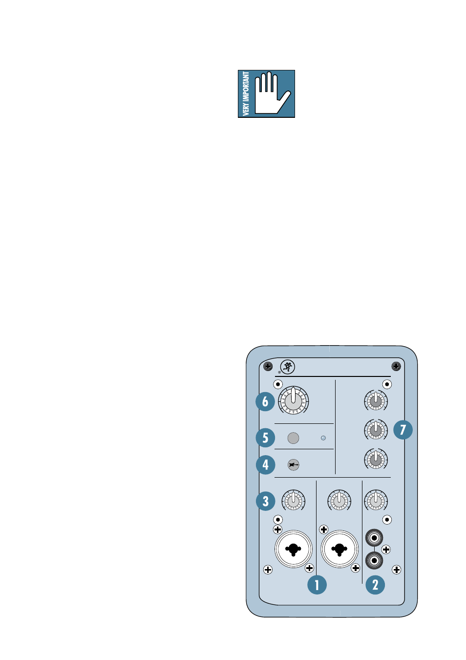
Page 8: Channel gain controls, Instrument switch (ch 1), 48v phantom power switch and indicator
8
FRONT PANEL DESCRIPTION
Plugging a guitar straight into a
typical line-level input can result in
the loss of gain, especially at high
frequencies, resulting in a dull sound.
Normally, you must use a direct box
between a guitar and a mixer’s or preamplifier’s input,
which serves to convert the impedance of the guitar
from high to low. The Instrument input on channel 1
makes the need for a direct box unnecessary. It’s like it
has its own built-in direct box!
However: The Instrument input is unbalanced, so if you
are running a long cord between the instrument and the
SRM150 (say over 20 feet), it is best to use a direct box
with a balanced output to avoid picking up noise over
the length of the cord.
5. 48V PHANTOM POWER Switch and
Indicator
Most professional condenser microphones require phan-
tom power, which is a low-current DC voltage delivered
to the microphone on pins 2 and 3 of the XLR micro-
phone connector. Push in the 48V button if your micro-
phone requires phantom power. An LED lights next to
the button to indicate that phantom power is active.
Most of the connections and controls on the SRM150
are located on the front panel for easy access.
1. MIC/LINE Inputs
Channels 1 and 2 have combo connectors, which
accept balanced microphone inputs from an XLR
connector, or balanced and unbalanced line-level inputs
from a 1/4" TRS or TS connector.
The XLR inputs are wired as follows:
Pin 1 = Shield or ground
Pin 2 = Positive (+ or hot)
Pin 3 = Negative (– or cold)
The 1/4" inputs are wired as follows and will accept
both balanced and unbalanced inputs:
Sleeve = Shield or ground
Tip = Positive (+ or hot)
Ring = Negative (– or cold)
2. Stereo Input
Channel 3 has a pair of RCA connectors, which accept
a stereo line-level input from a CD player or MP3 player
(or any other line-level device).
3. Channel Gain Controls
These are used to adjust the signal level for each
individual channel. Since the SRM150 incorporates
Mackie’s world-class low-noise mic preamp technology,
you can connect either a line-level or a microphone-level
signal to the input, and use this control to adjust the
level correctly.
Follow the Quick Start guide on page 4 for setting
the gain controls. For most applications, it will be in
the 12 o’clock position. If you have a particularly high
line-level signal connected to the SRM150, you may
need to turn the control down to the 9 o’clock position.
If you have a low line-level or mic-level signal con-
nected, you may need to turn the gain control up to the
3 o’clock position.
4. INSTRUMENT Switch (CH 1)
Push in this button to change the 1/4" line input
on channel 1 to an instrument input. When the but-
ton is out, the 1/4" input accepts normal line-level
signals from low-impedance sources. When the button
is pushed in, the 1/4" input accepts high-impedance
signals from instruments with electric pickups, which
you would normally run through a DI box.
HIGH
12kHz
MID
2.5kHz
LOW
100Hz
MAX
MIN
U
+15
-15
U
+15
-15
U
+15
-15
MAX
MIN
MAX
MIN
MAX
OFF
LEVEL
EQ
MIC/LINE
MIC/LINE
1
2
3
L
R
PHANTOM POWER
INSTRUMENT (CH 1)
48V
SRM150
MAIN
COMPACT ACTIVE PA SYSTEM