Rear panel description, Power switch, Fuse – MACKIE Srm150 User Manual
Page 10: Ac power receptacle, Thru connector, Mic/line switch, Main in
10
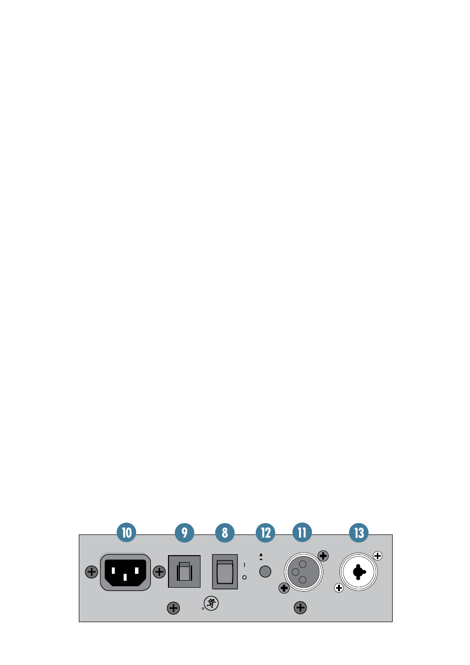
REAR PANEL DESCRIPTION
THRU
POWER
FUSE
MAIN IN
LINE
MIC
3
A
M
P
SRM150
8. POWER Switch
Switch up to turn the SRM150 on. Make sure the
MAIN LEVEL [6] control is down before you turn it on.
Press the bottom of this switch to put the SRM150
into standby mode. It will not function, but the circuits
are still live. To remove AC power, either turn off the
AC mains supply, or unplug the power cord from the
SRM150 and the AC mains supply.
When the POWER switch is turned on, and the line-
cord is connected to an active AC Mains supply, the cool
blue LED on the front of the speaker glows to let you
know that you’re ready to rock and roll.
9. FUSE
This is a resettable circuit breaker that monitors the
amount of current being drawn by the SRM150. Under
normal operating conditions, this should never pop. An
unusual condition may cause the breaker to pop, such
as a mains voltage surge occurring at the same time as a
peak amplifier output.
To reset the breaker:
• Turn the POWER [8] switch off and push the FUSE
switch to its UP position.
• Turn the POWER switch back on and the SRM150
should resume normal operation. If the circuit
breaker pops again, there may be something wrong
inside the SRM150. Refer to “Repair” on page 15.
10. AC Power Receptacle
This is a standard 3-prong IEC connector. Connect
the detachable linecord (included with your SRM150)
to the power receptacle, and plug the other end of the
linecord into an AC outlet. The SRM150 has a universal
power supply that can accept any AC voltage ranging
from 100VAC to 240 VAC. No need for voltage select
switches. It will work virtually anywhere in the world.
Note: If you happen to lose the AC linecord, replace-
ments are readily available at any office or computer
supply store. Always use a three-pin plug with a ground
pin.
11. THRU Connector
This is a male XLR connector that produces the main
signal just prior to the EQ [7] controls and the MAIN
LEVEL [6] control. The signal at the THRU connector
includes the input signals connected to channels 1-3
[1/2] and the MAIN IN [13] signal.
Use this connector to patch the signal from the
SRM150 to another SRM150 or other active loudspeaker
(like an SRM350 or SRM450), or to a mixer.
12. MIC/LINE Switch
The MIC/LINE switch affects the output level of the
THRU connector. Leave the switch out (LINE) when
connecting the THRU connector to another SRM150
or to a line-level input on a mixer. Push the switch in
(MIC) when connecting the THRU connector to a mi-
crophone input on a mixer or a stage snake.
13. MAIN IN
This is a combo connector that accepts a balanced
line-level signal from an XLR connector or a 1/4" TRS
connector. The signal is mixed with the signals from
channels 1-3 on the main mix bus, just prior to the
THRU [11] output, EQ [7] controls and the MAIN
LEVEL [6] control.