McIntosh MCD201 User Manual
Page 9
9
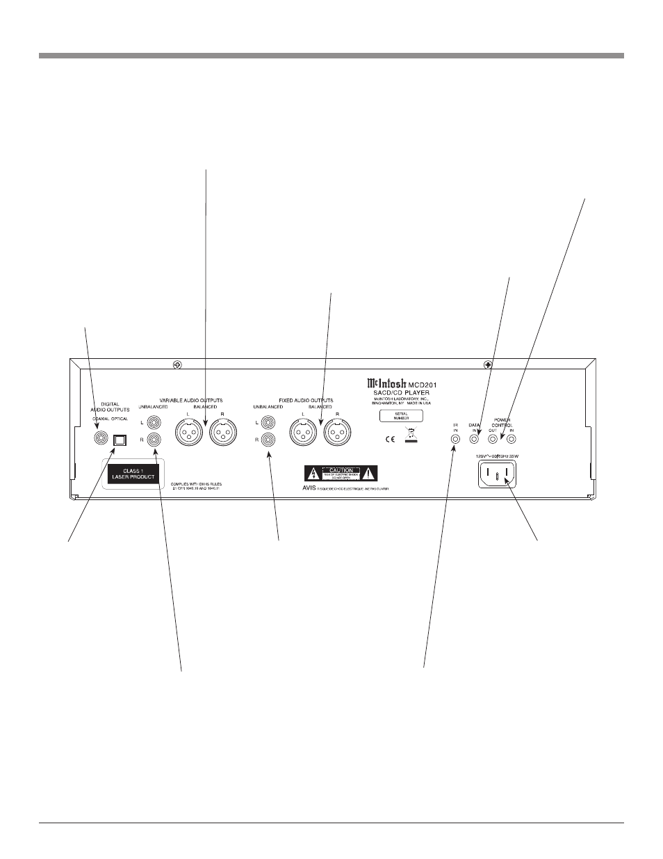
Rear Panel Connections
POWER CONTROL IN
receives turn-on signals
from a McIntosh compo-
nent and POWER CON-
TROL OUT sends turn-on
signals on to another
McIntosh Component
Connect the MCD201
power cord to a live AC
outlet. Refer to informa-
tion on the back panel of
your MCD201 to deter-
mine the correct voltage
for your unit
IR INput for
connecting an IR
Receiver
DATA IN receives
operating data from
a McIntosh Control
Center
COAXIAL DIGI-
TAL AUDIO OUT-
PUT sends signals
to a Control Center
with a D/A Con-
verter or a decoder
OPTICAL DIGITAL
AUDIO OUTPUT
sends signals to a Con-
trol Center with a D/A
Converter or a decoder
BALANCED VARIABLE level
AUDIO OUTPUTS supply ana-
log audio signals to connect to
Balanced Inputs of other compo-
nents
BALANCED FIXED level AU-
DIO OUTPUTS supply analog
audio signals to Balanced Inputs
of other components
UNBALANCED VARIABLE
level AUDIO OUTPUTS supply
analog audio signals to Unbal-
anced Inputs of other components
UNBALANCED FIXED level
AUDIO OUTPUTS supply ana-
log audio signals to Unbalanced
Inputs of other components