Sync card, Other connections, Foot switch 1 and 2 – MACKIE X.200 User Manual
Page 6: Serial 9 pin, Midi in and out, Ethernet, Iec power receptacle, Digital x bus
6
X.200
Digital X Bus
8. SYNC CARD
The Sync card provides the digital word clock in
and out on a pair of BNC connectors, and SMPTE
time code in and out on a pair of 1/4" jacks.
Sync data is also transmitted through the ADAT
lightpipe and AES/EBU connections. The Sync card
just provides another means to transmit and receive
the word clock. This is particularly useful when you
want the Digital X Bus to be the master clock for
your digital audio system.
Time code is also provided through MIDI time
code (MTC). SMPTE time code is more commonly
used in motion picture and broadcast applications.
Other Connections
In addition to the cards in the card slots, there are
more connections you can make on the rear panel.
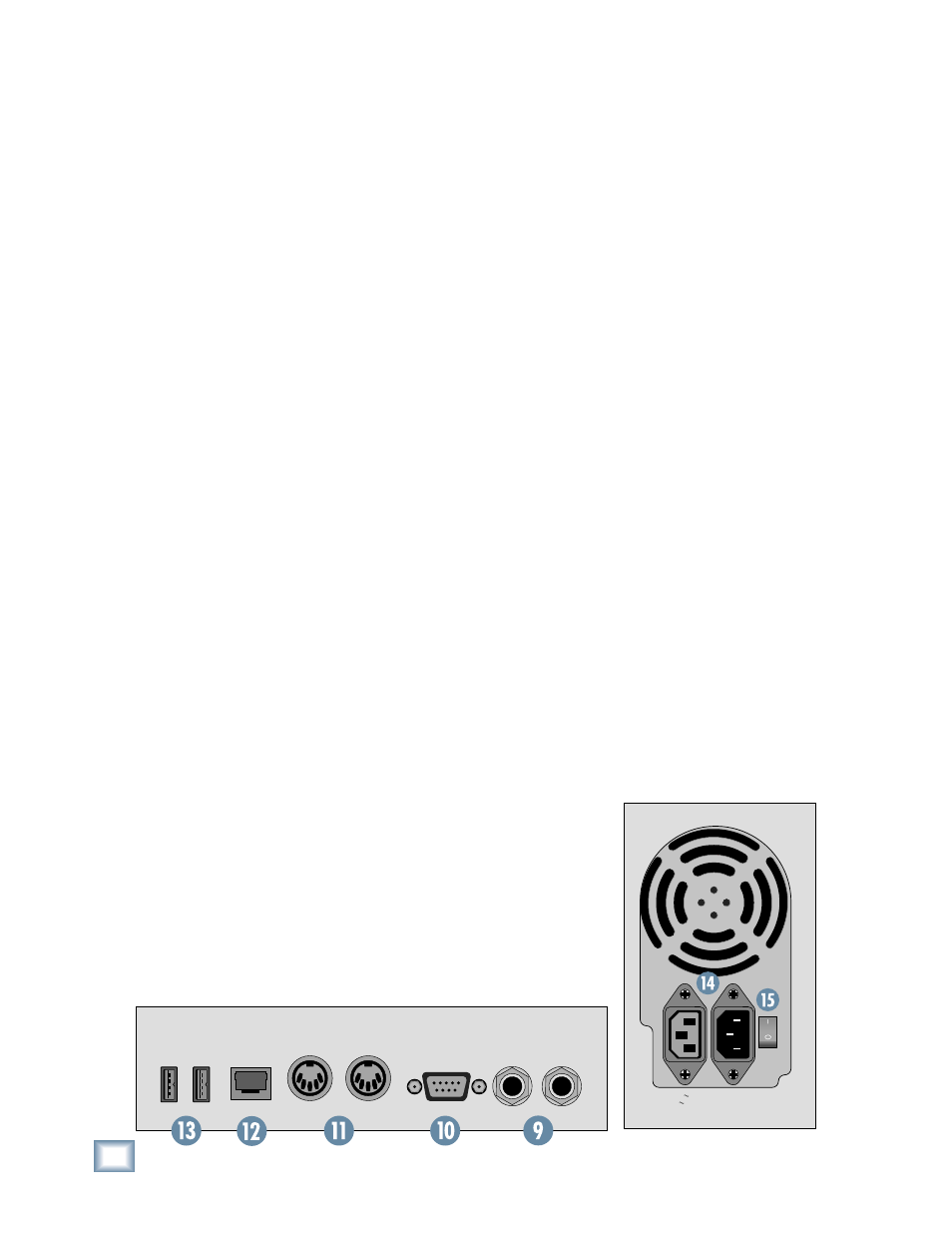
9. FOOT SWITCH 1 and 2
These two 1/4" TS jacks are provided for foot-
switch control of various functions. These functions
are assignable in the Windows > Setup window, and
include Talkback, Play/Stop, Next Marker, Previous
Marker, and New Marker.
10. SERIAL 9 PIN
This DB9 connector is an RS-422 port that sup-
ports the Sony® 9-Pin device protocol. It is con-
fi gured to operate as a controller, so it should be
connected to a device (DEV) that is confi gured to
be controlled by a controller (CONT). This is used
primarily to transmit tape transport commands from
the Digital X Bus to a recorder.
11. MIDI IN and OUT
These standard MIDI connectors (female 5-pin
DIN) can be used to send or receive MIDI Time
Code (MTC) and MIDI Machine Control (MMC)
when connecting to equipment with transport con-
trols and a position display.
The MIDI connectors can also be used to control
your DAW application when the MIDI fader bank is
selected (DAW Bank).
You can turn MTC on and off in the Sync Card
setup window (Windows > I/O Confi guration and
touch the Sync card) by clicking the Generate MTC
box. You can select MTC as the time code source in
the same setup window by clicking the Time Code
Source dropdown box and selecting MIDI (MTC).
12. ETHERNET
The Ethernet connector is reserved for future
upgrades.
13. USB
The two USB ports on the Digital X Bus can be
used to connect a USB equipped mouse, keyboard,
or USB memory stick (USB fl ash drive). See “More
Connections” on the next page to see how to con-
nect more USB devices, and a PS/2-style keyboard
and mouse with a 6-pin miniDIN connector.
14. IEC Power Receptacle
There are two power receptacles on the Digital X
Bus, one to provide power to the Digital X Bus and
the other to connect to another device and provide
power to it. These are standard 3-prong IEC power
connectors. Connect the detachable linecord (in-
cluded with your Digital X Bus) to the male power
receptacle, and plug the other end of the linecord
into an AC outlet with the correct voltage for your
particular Digital X Bus.
To connect another device to the female IEC
power receptacle, you need a power cord with a
male IEC power connector on one end, and a female
IEC power connector on the other end. These can be
purchased at most electronic supply stores.
MIDI
IN
FOOT SWITCH
1 2
MIDI
OUT
USB
ETHERNET
SERIAL 9-PIN
115V 9
V 9amp 6
p 60Hz
230V 4.5
V 4.5amp 5
p 50Hz
1100
1100W M
W Max