Hard disk connectors: ide1 & ide2, Serial port header: jcom1 (optional) – MSI MS-7181 User Manual
Page 31
2-15
Hardware Setup
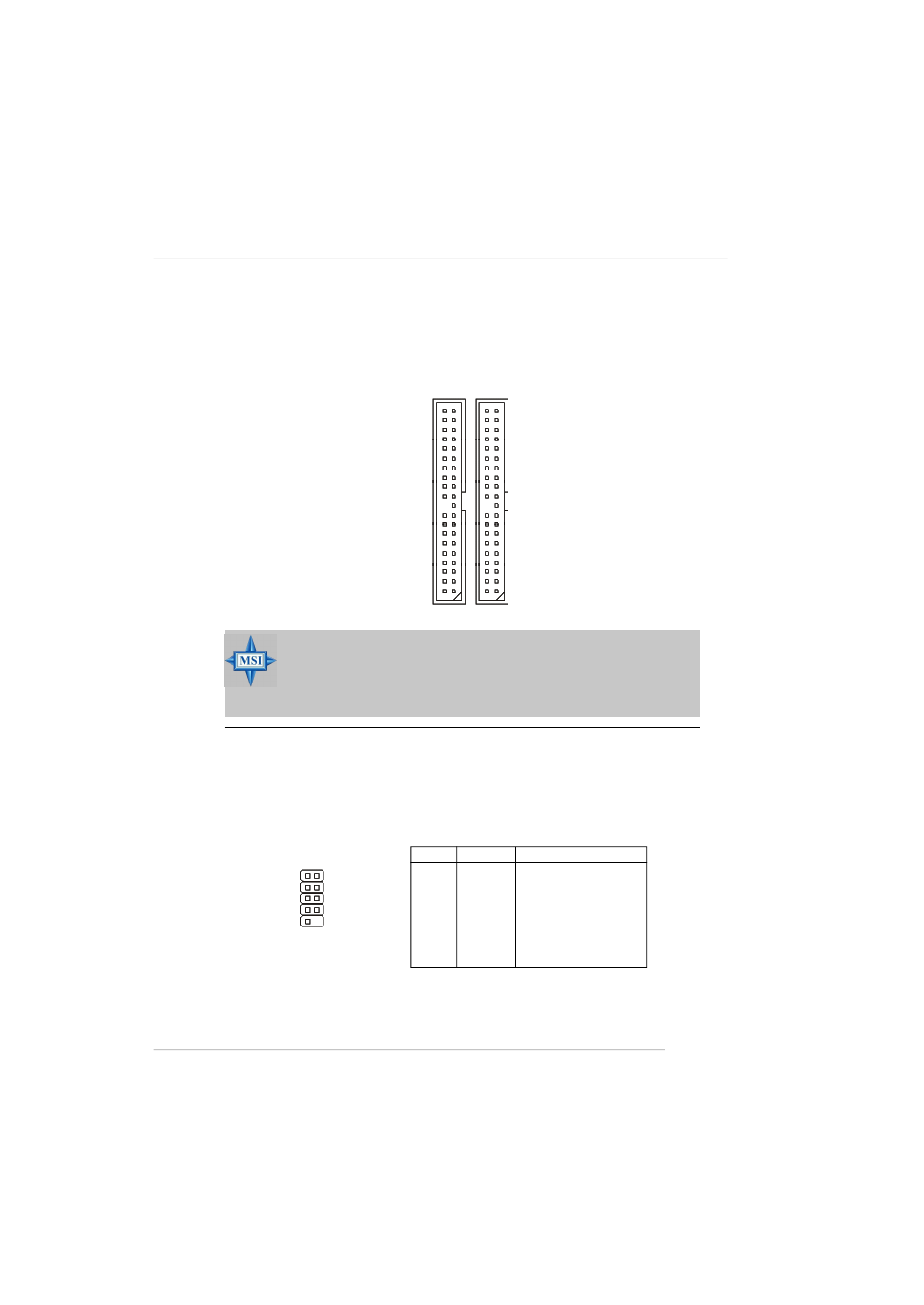
Hard Disk Connectors: IDE1 & IDE2
The mainboard provides a 32-bit Enhanced PCI IDE and Ultra DMA 33/66/100/133
controller that supports PIO mode 0 ~ 4, Bus Master, and Ultra DMA 33/66/100/133
function. You can connect up to four hard disk drives, CD-ROM drives, 120MB floppy
disk drive (reserved for future BIOS), and other devices.
IDE2
IDE1
MSI Reminds You...
If you install two hard disks on cable, you must configure the second
drive to Slave mode by setting its jumper. Refer to the hard disk
documentation s upplied by hard disk vendors for jumper s etting
instructions.
Serial Port Header: JCOM1 (Optional)
The mainboard offers one 9-pin header as serial port. The port is a 16550A high
speed communication port that sends/receives 16 bytes FIFOs. You can attach a
serial mouse or other serial device directly to it.
Pin Definition
PIN
SIGNAL
DESCRIPTION
1
DCD
Data Carry Detect
2
SIN
Serial In or Receive Data
3
SOUT
Serial Out or Transmit Data
4
DTR
Data Terminal Ready)
5
GND
Ground
6
DSR
Data Set Ready
7
RTS
Request To Send
8
CTS
Clear To Send
9
RI
Ring Indicate
JCOM1
1
5
6
9