Custom wood frame installation instructions – Marvel Industries 6SWCE User Manual
Page 3
CUSTOM WOOD FRAME INSTALLATION INSTRUCTIONS
STEP 3: SELECTING AND PREPARING THE WOOD FRAME
OPTIONAL LOCK AND KEY
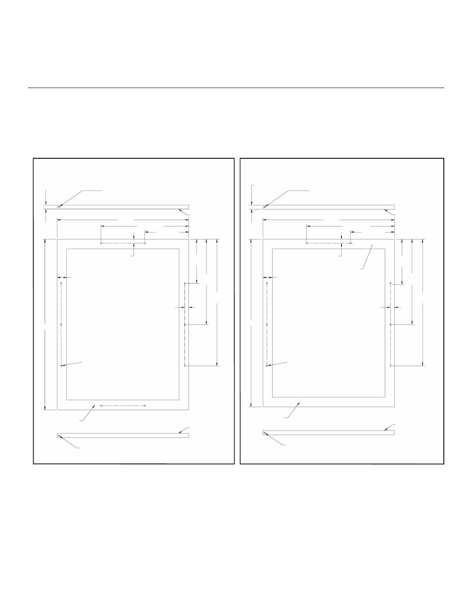
The optional lock and key helps protect your contents from tampering or misuse. The lock and key kit contains a lock cylin-
der, catch bracket, keys, and an installation nut. Some assembly is required as the lock and key is installed on the front of
the wood frame. See Figures 2 and 3 above for lock and key installation dimensions.
For a 3.5 inch Toe Kick
(Covers the Entire Door Extrusion)
Optional for a 4 inch Toe Kick
(To Match Existing Cabinetry
Toe Kick Height)
0.25 x 0.375 Deep Hinge Screw Clearance Hole.
Locate and drill using door hinge hole after the door
has been aligned to the unit and when the wood is
positioned on door.
0.25 x 0.375 Deep Hinge Screw Clearance Hole.
Locate and drill using door hinge hole after the door
has been aligned to the unit and when the wood is
positioned on door.
0.63 Min
0.75 Max
0.63 Min
0.75 Max
0.25 x 0.375 Deep Hinge Screw Clearance Hole.
Locate and drill using door hinge hole after the door
has been aligned to the unit and when the wood is
positioned on door.
0.25 x 0.375 Deep Hinge Screw Clearance Hole.
Locate and drill using door hinge hole after the door
has been aligned to the unit and when the wood is
positioned on door.
Mounting
Surface
(Non-Face) Side
Mounting
Surface
(Non-Face) Side
Mounting
Surface
(Non-Face) Side
Mounting
Surface
(Non-Face) Side
Pre-Drilled
Pilot Holes
8 Places
Pre-Drilled
Pilot Holes
8 Places
Top
Surface
1.72 Minimum
Width to Cover
Door Extrusion
1.72 Minimum
Width to Cover
Door Extrusion
0.72
0.72
Mounting
Surface
(Non-Face) Side
Mounting
Surface
(Non-Face) Side
30.31
29.81
0.72
0.72
23.44
23.44
15.63
15.63
7.81
7.81
7.81
7.81
15.16
15.16
22.50
22.50
2