Ld-3 – Meyer Sound M2D User Manual
Page 3
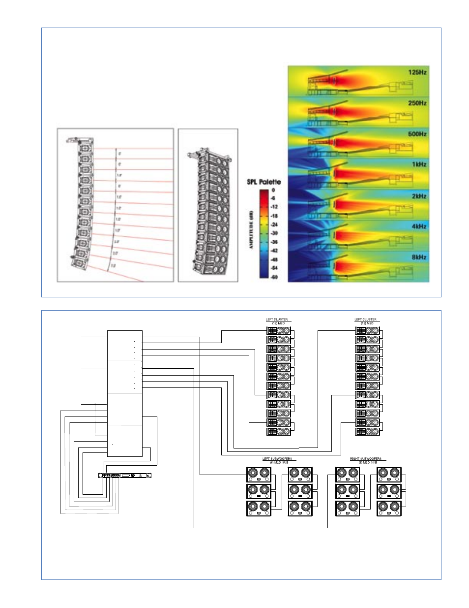
Signal Flow for a Typical
Integrated Reinforcement System
M2D Vertical Splay and Coverage
Because the M2D is compatible with most other Meyer Sound reinforcement loudspeakers, sound designers have maximum freedom to
customize systems for their needs. This block diagram illustrates the signal flow for a typical integrated sound reinforcement system
using 12 M2Ds per side for the main arrays.
These illustrations show how the splay between adjacent cabinets in
an M2D array may be adjusted to tailor coverage for a specific venue.
The MAPP Online plots on the right illustrate the vertical directivity
characteristics of the array on the left, with a section view of the
venue superimposed.
Digital Delay
2 In x 6 Out
Digital Delay/EQ
LD-3
Channel A
IN
SUB OUT
CH 1 OUT
CH 2 OUT
CH 3 OUT
Channel B
IN
SUB OUT
CH 1 OUT
CH 2 OUT
CH 3 OUT
Channel A
INSERTS
SENDS
IN SUB
OUT
Full Range
IN CH 1
OUT
Post Array
IN CH 2
OUT
Post Array
IN CH 3
Post HPF
Channel B
INSERTS
SENDS
IN SUB
OUT
Full Range
IN CH 1
OUT
Post Array
IN CH 2
OUT
Post Array
IN CH 3
Post HPF
Main
Left
Right
Optional
Subwoofer
Mono