Cable connector configurations (host end), Cable connector configurations – Metrologic Instruments MS1690 User Manual
Page 40
36
S
CANNER AND
C
ABLE
T
ERMINATIONS
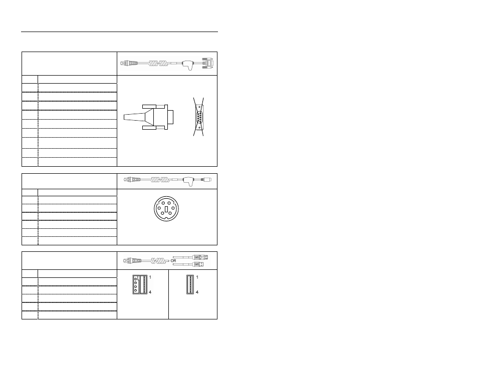
Cable Connector Configurations (Host End)
“Standard” PowerLink Cable
53-53000-3 Coiled
Pin Function
1 Shield
Ground
2
RS232 Transmit Output
3
RS232 Receive Input
4
DTR Input/Light Pen Source
5 Power/Signal
Ground
6 Reserved
7
CTS Input
8 RTS
Output
9 +5VDC
Stand Alone Keyboard PowerLink
Cable
53-53020-3
Pin Function
1 PC
Data
2 NC
3 Power
Ground
4
+5VDC PC Power to KB
5 PC
Clock
6 NC
USB Power/Communication Cable
53-53213-N-3, 53-53214-N-3 or
53-53235-N-3
Pin Function
1 PC
+5V/V_USB
2 D-
3 D+
4 Ground
Shield Shield
USB Type A
Locking with Power
USB
Non-Locking
9-Pin D-Type Connector
9
5
6
1
4
2
1
3
6 5
6-Pin Male Mini-DIN Connector
See also other documents in the category Metrologic Instruments Scanners:
- VoyagerCG MS9500 (2 pages)
- MS2122 (2 pages)
- IS4910 Series (42 pages)
- MS7600 (2 pages)
- StratosH MS2300 Series (1 page)
- IS4815 (48 pages)
- MS6130 MX003 (44 pages)
- MLPN 2168 (20 pages)
- StratosS MS2221 (68 pages)
- ARGUSSCANTM MS7220 (52 pages)
- MS2421 (66 pages)
- FocusBT MS1633 (52 pages)
- Stratos MS2xxx Series (88 pages)
- MS9535 (56 pages)
- 1070 (21 pages)
- MS7100 (45 pages)
- MLPN 2159 (28 pages)
- MS9524 (56 pages)
- MS700i (60 pages)
- MS9500 (2 pages)
- 185 (1 page)
- StratosS MS2220 (86 pages)
- MX003 (45 pages)
- StratosS MS2200 Series (2 pages)
- MS9500 Voyager (56 pages)
- TECH 7 (32 pages)
- MS6520 (48 pages)
- SP5500 (2 pages)
- IS3480-00 (56 pages)
- IS1650 (2 pages)
- IS8000 Series (40 pages)
- MS7120 Series (48 pages)
- IS4921 (61 pages)
- Laser Scanner (56 pages)
- MS 5145 (2 pages)
- MS860 (55 pages)
- MS3580 (56 pages)
- MS3580 (2 pages)
- MS1890 (48 pages)
- MS6720 (52 pages)
- Cubit IS6520 Series (44 pages)
- IS8000 (40 pages)
- MS1890 Focus (2 pages)
- Hand-Held Scanner (13 pages)