4. connection diagram – Miller Electric Remote Operator Interface User Manual
Page 15
OM-217 834 Page 11
Ref. 803 697-E
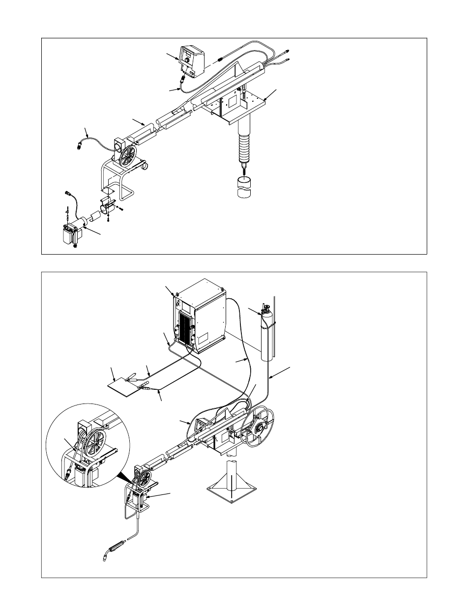
Typical Swingarc installation shown;
however, various installations are
possible depending on the
application.
1
Remote Operator Interface
2
Swingarc Swivel Assembly
3
Boom
4
AA40G Wire Drive Assembly
5
Trigger Cable
4-3. Remote Operator Interface And Wire Drive Installation
1
2
3
4
5
5
803 698-E
1
Welding Power Source
2
Wire Feeder
3
Gas Cylinder
4
Gas Hose
5
Network Feeder Cable
6
Negative (−) Weld Cable
7
Workpiece
8
Voltage Sensing Lead
(Optional)
.
Positive (+) voltage sensing
lead is contained in the motor
cable.
9
Positive (+) Weld Cable
10 Motor Cable
11 Trigger Cable
4-4. Connection Diagram
1
2
3
4
5
7
8
9
6
10
11
11