Milwaukee 7150-21 User Manual
Page 4
6
7
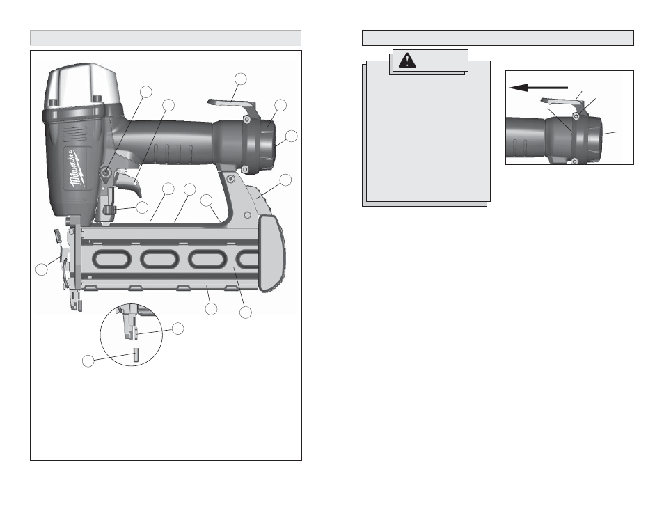
FUNCTIONAL DESCRIPTION
15
11
9
2
3
1
1. No-mar
pad
2. Workpiece
contact
3. Jam-clearing
door
4. Actuation
selector
5. Trigger
6. Belt
hook
7. Exhaust
defl ector
8. Air
inlet
9. Pusher release button
10. Pusher assembly
11. Magazine
12. Extra no-mar pad storage (on back of magazine)
13. Nameplate (on back of magazine)
14. Warning label (on back of magazine)
15. Depth of drive adjustment
13
14
7
5
6
4
ASSEMBLY
No-Mar Pad
The No-Mar Pad on the nose of the tool
protects the workpiece when the nose is
compressed during actuation. The pad can
be removed and replaced.
1. Before removing or replacing no-mar
pads, disconnect the air supply from the
tool and remove fastener strips.
2. To
remove the pad, pull the pad off of
the workpiece contact.
3.
Storage for an additional pad is available
on the magazine of the tool.
4. To
replace the pad, fi t it into place over
the workpiece contact.
Exhaust
The exhaust cap can be adjusted to direct
the exhaust as desired. Turn the exhaust cap
to the desired locking position.
Fig. 1
Belt hook
Front of tool
End cap
Screw (2)
Air
inlet
Removing and Installing the Belt Hook
To remove the hook:
1. Rotate the hook until it snaps into one of
the preset positions.
2.
Remove the two mounting screws using
the wrench provided.
3. Pull the hook off the rear of the tool.
To install the hook:
1. Align the spring-loaded post on the hook
with a slot on the rear of the tool.
2.
Slide the hook onto the tool, making sure
the hook points toward the front of the
tool. Push the hook up against the end
cap.
3. Install the two mounting screws using
the wrench provided. Tighten securely.
4. Verify that the hook is installed correctly
by fi rmly pulling the hook toward the air
inlet. It must not move.
10
12
8
WARNING
Disconnect the air supply from the
tool and remove fastener strips
before changing or removing acces-
sories. Only use accessories spe-
cifi cally recommended for this tool
by the manufacturer. Others may be
hazardous.
The operator and other people in the
work area must wear eye protection
in accordance with ANSI Z87.1. Eye
protection does not fi t all operators
in the same way. Make sure the eye
protection chosen has side shields or
provides protection from fl ying debris
both from the front and sides.