MTD 050 thru 062 User Manual
Page 8
8
SECTION 6: ASSEMBLY INSTRUCTIONS
IMPORTANT:
This unit is shipped WITHOUT
GASOLINE or OIL. After assembly, service engine
with gasoline and oil as instructed in the separate
engine manual packed with your unit.
NOTE:
Reference to right or left hand side of the
mower is observed from the operating position.
This owner’s guide covers various models of
mowers. Follow only the instructions which pertain
to your unit.
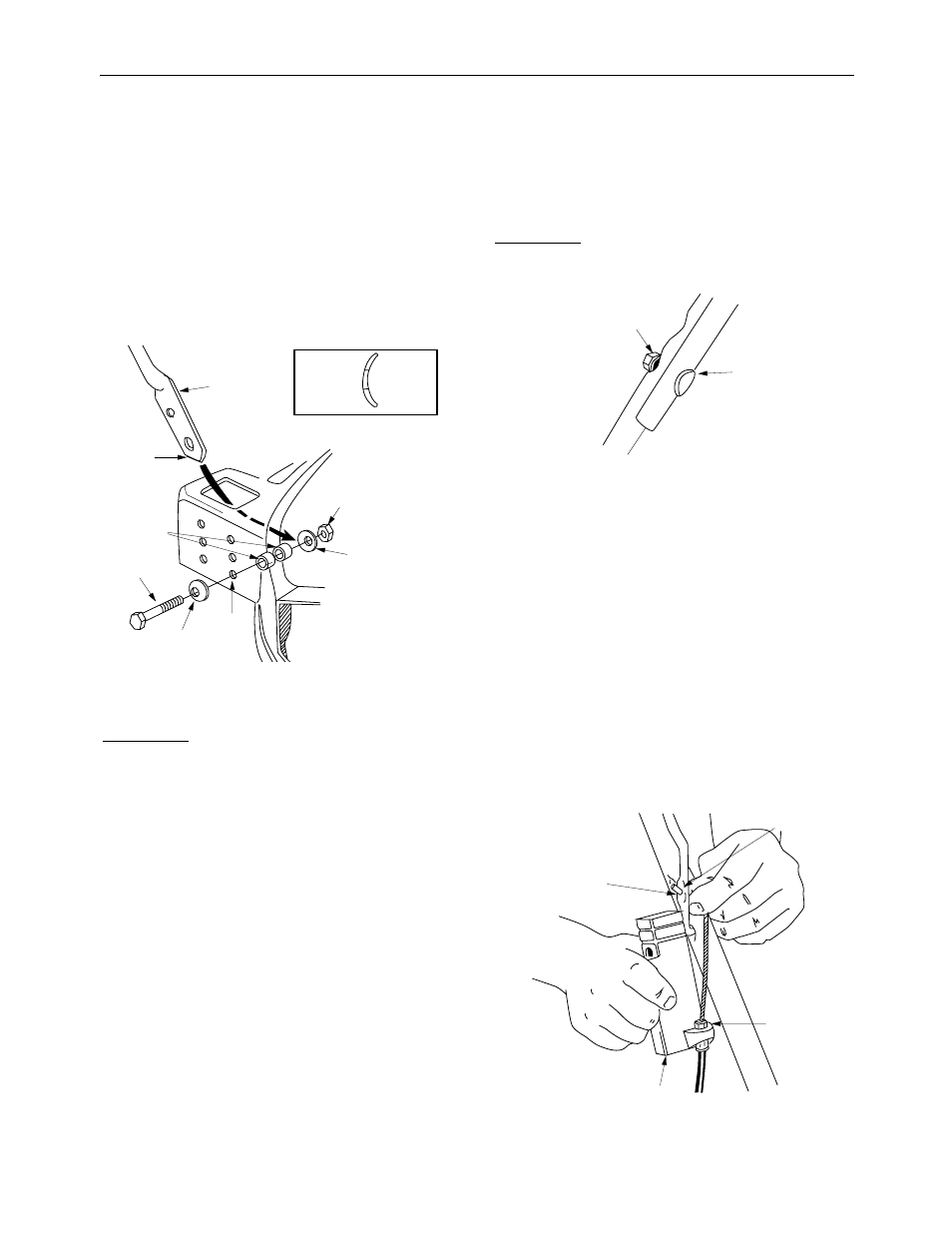
Figure 4
ATTACHING THE LOWER HANDLE
(Hardware A)
1.
Raise the rear of the deck and block securely.
2.
Place one cupped washer on each hex bolt 1-1/
2" long (crowned side of washer goes against
the head of the hex bolt).
3.
Insert the ends of the lower handle through the
slots in the rear of the deck.
NOTE:
It is helpful to have another person hold
the handle in position as you continue.
4.
Place
two
spacers between the bottom hole in
lower handle and
bottom inside hole
of the
deck. See Figure 4. Use a screwdriver to pry
the handle away from the deck if necessary.
5.
Using a screwdriver, line up the bottom inside
hole in the deck, the spacers and the bottom
hole in the handle, then insert hex bolt as
shown from the outside of the deck.
6.
Secure with cupped washer (cupped side
against the handle) and hex lock nut. Do not
tighten at this time.
7.
Repeat steps 4 through 6 to attach the other
side of the handle.
8.
Tighten both hex bolts and nuts securely.
ATTACHING THE UPPER HANDLE
(Hardware B
)
Figure 5
1.
Place the upper handle in position over the
lower handle. The hole in the side of the blade
control handle (attached to the upper handle)
must be on the
left
side.
2.
Secure the upper handle to lower handle using
the curved head bolts, split washers and hex
nuts as shown in Figure 5. The head of the
carriage bolts go on the outside of the handle.
ATTACHING THE CONTROL BOX
One end of the brake cable is attached to the
engine. The other end is attached to the control box.
Attach the control box to the upper handle as
follows.
Figure 6
Hex Lock Nut
Cupped
Side
Crowned
Side
Cupped Washer
Handle
Lower
Notch
Spacers
Two
Bolt
Hex
Cupped
Washer
Use
This
Hole
Cupped
Washer
Bolt
Hex
Hex Nut
Split Washer
Curved
Head
Bolt
Hole in
Blade
Control
Handle
“Z” End
of Brake
Cable
Plastic
Fitting
Control Box