McIntosh MA7000 User Manual
Page 7
7
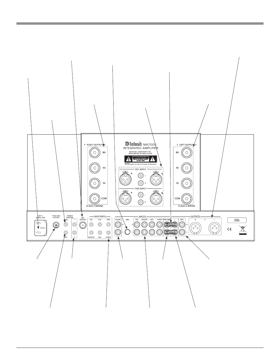
Rear Panel Connections
Connect the MA7000
power cord to a live
AC outlet. Refer to
information on the
back panel of your
MA7000 to determine
the correct voltage for
your unit
POWER CONTROL ACC
Output sends a turn-On,
turn-Off signal to a McIn-
tosh Component when using
the MA7000 Remote Control
ACC On/Off Push-buttons
DATA PORTS send
signals to McIntosh
Source Components
to allow control with
the MA7000 Remote
Control
PWR AMP
input accepts
signals from
the internal
Preamplifier
or a separate
external Pre-
amplifier
JUMPER PLUGS
connect the Pream-
plifier OUTPUT 1
Jacks to the PWR
AMP IN Jacks
and are needed for
normal operation
CD2, SERVER,
REC and TUNER
INPUTS accept high
level program source
signals
GND
terminal
accepts
a ground
wire from a
turntable
RECord
OUTPUT
sends signals
to the input
of a recording
device
RIGHT OUTPUT
connections for a
2, 4 or 8 ohm
loudspeaker
Main Fuse holder,
refer to information
on the back panel
of your MA7000 to
determine the cor-
rect fuse size and
rating
CD1 and DVD Bal-
anced and Unbalanced
INPUTS accept high
level program source
signals
PHONO accepts
signals from a
Moving Magnet
phono cartridge
OUTPUT 1 sends
signals to the internal
Power Amplifier or
a separate external
Power Amplifier
POWER CON-
TROL MAIN Out-
put sends a turn-on
signal to a McIn-
tosh Component
when the MA7000
is turned On
POWER CONTROL
1 and 2 Output sends
a turn-on signal to a
McIntosh Component
when the Outputs 1
and 2 Push-buttons
are used
EXT SENSOR con-
nector permits the
connection of a Mc-
Intosh IR Sensor for
remote operation
OUTPUT 2 sends balanced
signals to a separate exter-
nal Power Amplifier with
balanced inputs
LEFT OUTPUT
connections for a
2, 4 or 8 ohm
loudspeaker