Gateway SW203 User Manual
Page 4
4
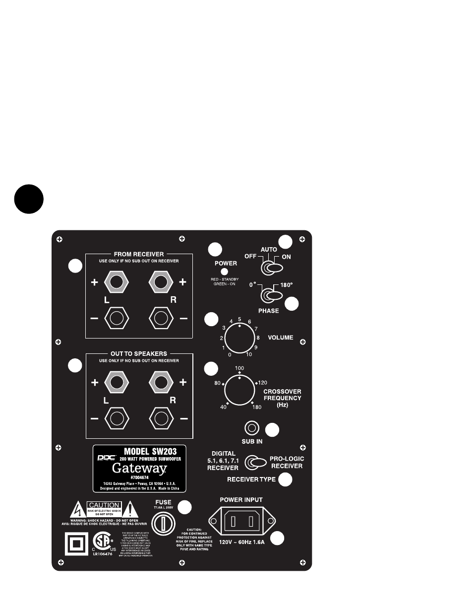
4. VOLUME CONTROL. Rotating this
knob clockwise increases the output level
of the subwoofer. To start out, make sure
that the VOLUME is turned all the way down
(fully counterclockwise). Later, after some
initial listening tests, you can adjust the vol-
ume to your own tastes. However, care
should be taken not to overdrive the sub-
woofer to the point of audible distortion.
5. CROSSOVER FREQUENCY CONTROL
This control determines what lower part of
the frequency spectrum will be reproduced
by the SW103/SW203/SW303 and what high-
er parts will be handled by your main
speaker. It is a “crossover” control. Rotating
the knob sets the point where all lower fre-
quencies will be handled by the subwoofer
and all higher frequencies will be routed to
your main stereo speakers.
As a starting point, set the control around
80 Hz. if you are using left and right tower
speakers, 100 Hz. with bookshelf speakers,
and 120 Hz. with small mini-speakers.
Note: If you use the SUB IN connector, the
RECEIVER TYPE toggle switch must be in the
Pro Logic mode for the crossover frequency
control to operate.
6. SUB IN. This connection is used
to connect the subwoofer to the receiver.
7. RECEIVER TYPE TOGGLE SWITCH.
You must set this switch to the type of
receiver mode you are using.
Note: When this switch is set to DIGITAL
RECEIVER 5.1, 6.1, 7.1, the CROSSOVER
FREQUENCY control (9) does not affect
the signal.
8. POWER INPUT. This connector is the
AC power in. Your subwoofer is supplied
with a removable power cord that mates to
this plug.
9. REMOVABLE FUSE HOLDER. By pushing
in and turning counter-clockwise, you can
remove and replace the fuse. Check the rat-
ing on the fuse for proper size of your unit.
10. FROM RECEIVER. Connects to a
receiver’s speaker terminals. These binding
post, color-coded connectors are used to
hook the subwoofer to another receiver that
may not have subwoofer out or LFE (Low
Frequency Effects) output connections.
11. OUT TO SPEAKERS. If you are using
the SW103/SW203/SW303 from receiver
inputs, you will hook your main speakers to
these binding post, color-coded connections.
They are NOT used if you are using the LFE
(SUB) IN line level connection.
switch is in the AUTO position, the amplifier
will stay turned on as long as a signal is
being fed to the subwoofer amplifier. 15 to
20 minutes after you stop playing music or
a video, the amplifier goes into STANDBY
mode – see (1). When you again begin to
play music or a video, the amplifier will
automatically turn on.
3. PHASE SWITCH. This switch is used to
set the subwoofer’s phase to either normal
“0º” or reverse “180º” (out of) phase.
Once you determine the placement of the
SW103/SW203/SW303, you will need to try
both positions of this switch for the best bass
output for your listening position. The physical
location of your subwoofer and main speak-
ers determines the phase setting that will
sound best at your main listening position. If
this requires using the “180º” mode, don’t
worry, there is nothing “abnormal” about it.
10
11
9
1
2
3
4
5
6
7
8
DRAWING 2 - SW203/SW303 rear panel
SW203/SW303
AMPLIFIER
PANEL TOUR
Before actual setup, you should
familiarize yourself with the connections on
the back of the SW103/SW203/SW303, as
shown in Drawing 2.
1
. POWER INDICATOR. When the amplifier
is ON, this indicator will be green. When the
amplifier is in the STANDBY mode, as men-
tioned in item 2, this indicator will be red.
2. POWER/AUTO ON SWITCH. This toggle
switch turns the SW103/SW203/SW303 on
and off. When the switch is in the ON posi-
tion, the amplifier will stay on as long as the
switch remains in that position. When this