Grizzly H7507 User Manual
Page 19
Model h7507 (Mfg. since 3/05)
-17-
&
¿
-
&
¿
-
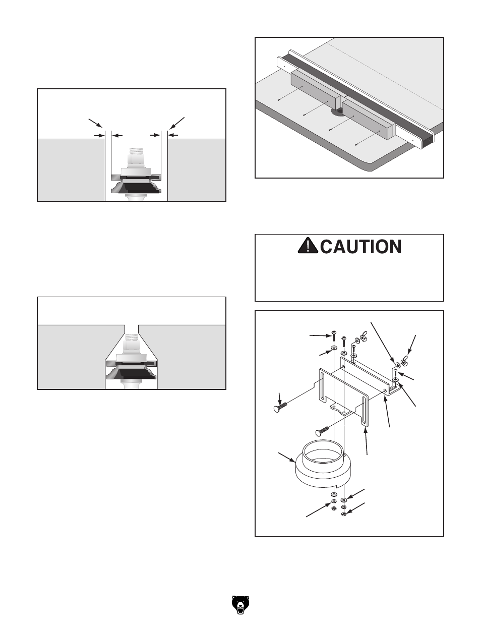
BVm^bjb9^hiVcXZ
[gdbGdjiZg7^i
BVm^bjb9^hiVcXZ
[gdbGdjiZg7^i
Dji[ZZY;ZcXZ
>c[ZZY;ZcXZ
figure 25. positioning fences around router bit.
16. position the infeed and outfeed fences as
close as possible to the maximum diameter
of the router bit, but not farther than
1
⁄
8
" (see
figure 25).
Dji[ZZY;ZcXZ
>c[ZZY;ZcXZ
figure 26. Minimum clearance fence setup.
For maximum safety and support, consider
using a minimum clearance design for your
fences. Minimum clearance fences are cut
around the shape of the router bit to minimize
clearance between the router bit and the
fence, as shown in
figure 26.
18. assemble the router guard with the compo-
nents shown in
figure 28.
Note: If you followed Step 13, be sure to
install the modified board on the infeed side.
>c[ZZYH^YZ
Dji[ZZYH^YZ
figure 27. attaching fence boards.
E]ae=YHXg
-"('m
*
¿
-
8Vgg^V\Z7dai
&
¿
)
"'%m
&
¿
'
L^c\Cji
&
¿
)
"'%
;aViLVh]Zg-
;aViLVh]Zg
-
;aViLVh]Zg-
AdX`LVh]Zg- =ZmCji-"(' KZgi^XVa 7gVX`Zi =dg^odciVa 7gVX`Zi ;aViLVh]Zg & ¿ ) LddY HXgZl -m ( ¿ ) figure 28. assembling router guard. Overtightening the fasteners that secure the plastic guard to the bracket may crack or break the plastic guard, rendering it unsafe for use. 17. Clamp, predrill with a countersinking bit, and attach the fence pieces with at least two figure 27. (only use wood screws that are long
wood screws per side, as shown in
enough to thread into the support board, but
not so long that they enter the plastic fence
face.)