English, 7 connectors introduction – GIGABYTE GA-8I945PLGE-RH User Manual
Page 18
GA-8I945PLGE-RH Motherboard
- 18 -
English
1-7
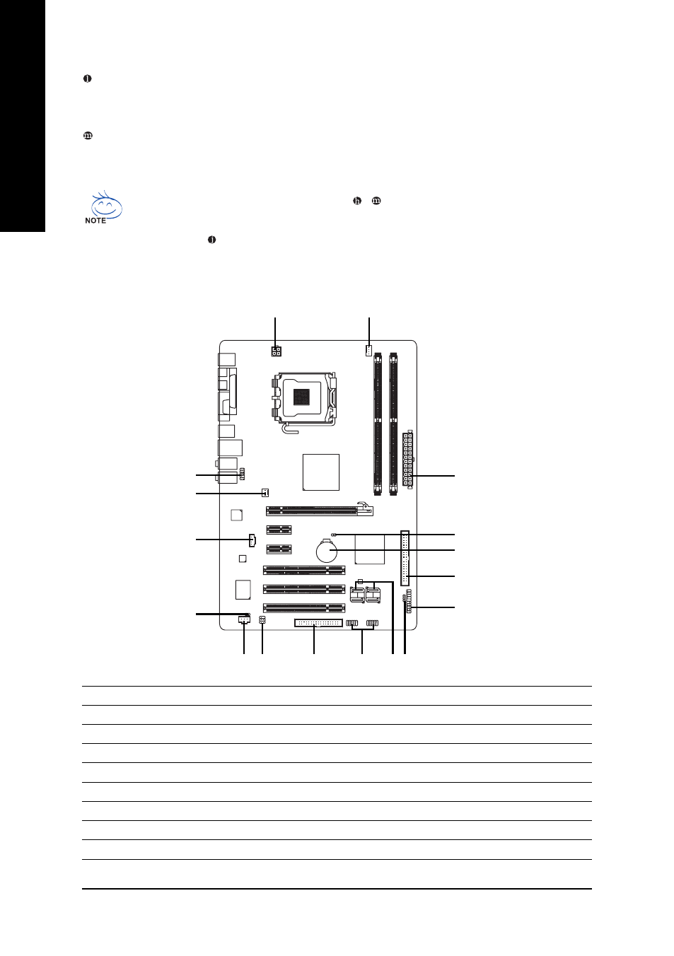
Connectors Introduction
Center/Subwoofer Speaker Out
The default Center/Subwoofer Speaker Out jack. Center/Subwoofer speakers can be connected to
Center/Subwoofer Speaker Out jack.
Side Speaker Out
The default Side Speaker Out jack. Surround side speakers can be connected to Side Speaker Out
jack.
In addition to the default speakers settings, the ~ audio jacks can be reconfigured to perform
different functions via the audio software. Only microphones still MUST be connected to the de-
fault Mic In jack ( ) . Please refer to the 2-/4-/6-/8- channel audio setup steps for detailed software
configuration information.
1)
ATX_12V
2)
ATX (Power Connector)
3)
CPU_FAN
4)
SYS_FAN
5)
FDD
6)
IDE1
7)
SATAII0 / SATAII1 / SATAII2 / SATAII3
8)
F_AUDIO
9)
PWR_LED
10)
F_PANEL
11)
CD_IN
12)
SPDIF_I
13)
F_USB1/F_USB2
14)
RF_ID
15)
CI
16)
CLR_CMOS
17)
BAT
8
1
2
3
4
5
6
7 9
10
11
12
13
14
15
16
17
- GA-8I915GM (80 pages)
- AGP 4X(1.5V) (112 pages)
- GA-M68MT-D3P (40 pages)
- Xeon Processor Motherboard GA-5YXS1-RH (54 pages)
- GA-MA770T-UD3P (100 pages)
- GA-K8VM800M (96 pages)
- GN-AP101B (39 pages)
- GA-P31-ES3G (84 pages)
- GA-K8NS ULTRA-939 (96 pages)
- GA-8I865GME-775-RH (64 pages)
- GA-EP45-UD3L (112 pages)
- GA-8I915MD-GV (80 pages)
- GA-8S661FXM-775 (88 pages)
- GN-B41G (84 pages)
- LGA775 Socket Motherboard for Intel GA-73PVM-S2H (100 pages)
- GA-965GM-S2 (88 pages)
- GeForceTM 6600 Graphics Accelerator GV-N66128DP (34 pages)
- GN-FE605(M) (38 pages)
- GN-FE605(M) (62 pages)
- 4635 (26 pages)
- 230 (14 pages)
- GA-8VM800M-775 (88 pages)
- AMD Socket 939 Processor Motherboard GA-K8N51PVM9-RH (96 pages)
- GA-8ANXP-D (88 pages)
- 5230 (97 pages)
- 7VM333M-RZ (36 pages)
- AMD Socket 754 Processor Motherboard GA-K8NE-RH (80 pages)
- Pentium 4/D Processor Motherboard GA-5EASV-RH (88 pages)
- GN-WPKG (26 pages)
- Intel Pentium 4 Processor Motherboard GA-8VM800M (80 pages)
- 8S648FXP-RZ (40 pages)
- AirCruiser G GN-WB01GS (26 pages)
- PHASER 4500 (128 pages)
- GV-R487D5-1GD (34 pages)
- GA-8IP775 Series (80 pages)
- GN-A11G (57 pages)
- GA-K8VT800 (80 pages)
- SmartSetup 3 (4 pages)
- GA-K8U-939 (88 pages)
- GA-K8NE (80 pages)
- GA-M61PME-S2P (88 pages)
- 7VM400M-RZ (36 pages)
- GA-K8NF-9 (88 pages)
- Pentium II / III Processors 6ZMM (23 pages)