English, 11) cd_in (cd in connector), 12) f_panel (front panel jumper) – GIGABYTE AMD Socket AM2 Processor Motherboard GA-M55SLI-S4 User Manual
Page 27: Hardware installation - 27
Hardware Installation
- 27 -
English
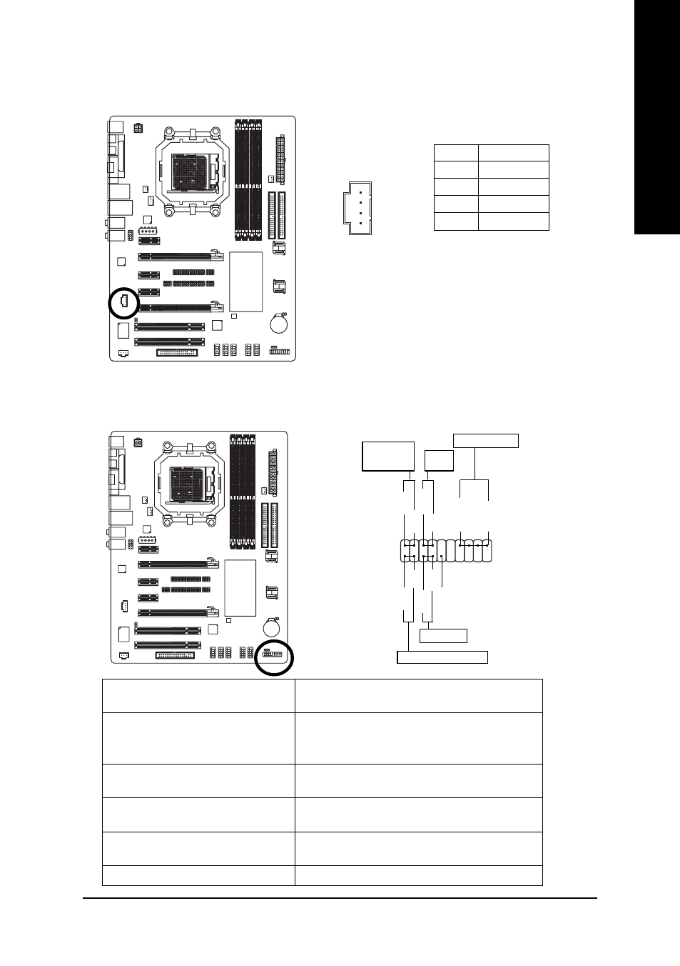
11) CD_IN (CD In Connector)
Connect CD-ROM or DVD-ROM audio out to the connector.
Pin No.
Definition
1
CD-L
2
GND
3
GND
4
CD-R
1
12) F_PANEL (Front Panel Jumper)
Please connect the power LED, PC speaker, reset switch and power switch etc of your chassis
front panel to the F_PANEL connector according to the pin assignment below.
HD (IDE Hard Disk Active LED) (Blue)
Pin 1: LED anode(+)
Pin 2: LED cathode(-)
SPEAK (Speaker Connector) (Amber)
Pin 1: Power
Pin 2- Pin 3: NC
Pin 4: Data(-)
RES (Reset Switch) (Green)
Open: Normal
Close: Reset Hardware System
PW (Power Switch) (Red)
Open: Normal
Close: Power On/Off
MSG(Message LED/Power/Sleep LED)
Pin 1: LED anode(+)
(Yellow)
Pin 2: LED cathode(-)
NC ( Purple)
NC
1
2
19
20
HD-
HD+
RES+
RES-
NC
IDE Hard Disk Active LED
Reset Switch
SPEAK-
MSG-
MSG+
PW-
PW+
Message LED/
Power/
Sleep LED
Speaker Connector
SPEAK+
Power
Switch
- GA-8I915GM (80 pages)
- AGP 4X(1.5V) (112 pages)
- GA-M68MT-D3P (40 pages)
- Xeon Processor Motherboard GA-5YXS1-RH (54 pages)
- GA-MA770T-UD3P (100 pages)
- GA-K8VM800M (96 pages)
- GN-AP101B (39 pages)
- GA-P31-ES3G (84 pages)
- GA-K8NS ULTRA-939 (96 pages)
- GA-8I865GME-775-RH (64 pages)
- GA-EP45-UD3L (112 pages)
- GA-8I915MD-GV (80 pages)
- GA-8S661FXM-775 (88 pages)
- GN-B41G (84 pages)
- LGA775 Socket Motherboard for Intel GA-73PVM-S2H (100 pages)
- GA-965GM-S2 (88 pages)
- GeForceTM 6600 Graphics Accelerator GV-N66128DP (34 pages)
- GN-FE605(M) (38 pages)
- GN-FE605(M) (62 pages)
- 4635 (26 pages)
- 230 (14 pages)
- GA-8VM800M-775 (88 pages)
- AMD Socket 939 Processor Motherboard GA-K8N51PVM9-RH (96 pages)
- GA-8ANXP-D (88 pages)
- 5230 (97 pages)
- 7VM333M-RZ (36 pages)
- AMD Socket 754 Processor Motherboard GA-K8NE-RH (80 pages)
- Pentium 4/D Processor Motherboard GA-5EASV-RH (88 pages)
- GN-WPKG (26 pages)
- Intel Pentium 4 Processor Motherboard GA-8VM800M (80 pages)
- 8S648FXP-RZ (40 pages)
- AirCruiser G GN-WB01GS (26 pages)
- PHASER 4500 (128 pages)
- GV-R487D5-1GD (34 pages)
- GA-8IP775 Series (80 pages)
- GN-A11G (57 pages)
- GA-K8VT800 (80 pages)
- GA-8I945PLGE-RH (80 pages)
- SmartSetup 3 (4 pages)
- GA-K8U-939 (88 pages)
- GA-K8NE (80 pages)
- GA-M61PME-S2P (88 pages)
- 7VM400M-RZ (36 pages)
- GA-K8NF-9 (88 pages)
- Pentium II / III Processors 6ZMM (23 pages)