Wheel characteristics, Belt drive: fan class, Direct drive: percent wheel width – Greenheck Fan Mixed Flow Fans Belt and Direct Drive QEI-L User Manual
Page 7: Sound power versus sound pressure
7
Wheel Characteristics
Static Pr
essur
e
CFM
50%
Wheel
Width
50% Wheel Width
100%
Wheel
Width
100% Wheel Width
Intermediate
Wheel
Widths
Static Pr
essur
e
CFM
50%
Wheel
Width
50% Wheel Width
100%
Wheel
Width
100% Wheel Width
Intermediate
Wheel
Widths
Static Pr
essur
e
CFM
50%
Wheel
Width
50% Wheel Width
100%
Wheel
Width
100% Wheel Width
Intermediate
Wheel
Widths
Static Pr
essur
e
CFM
Class II
Class I
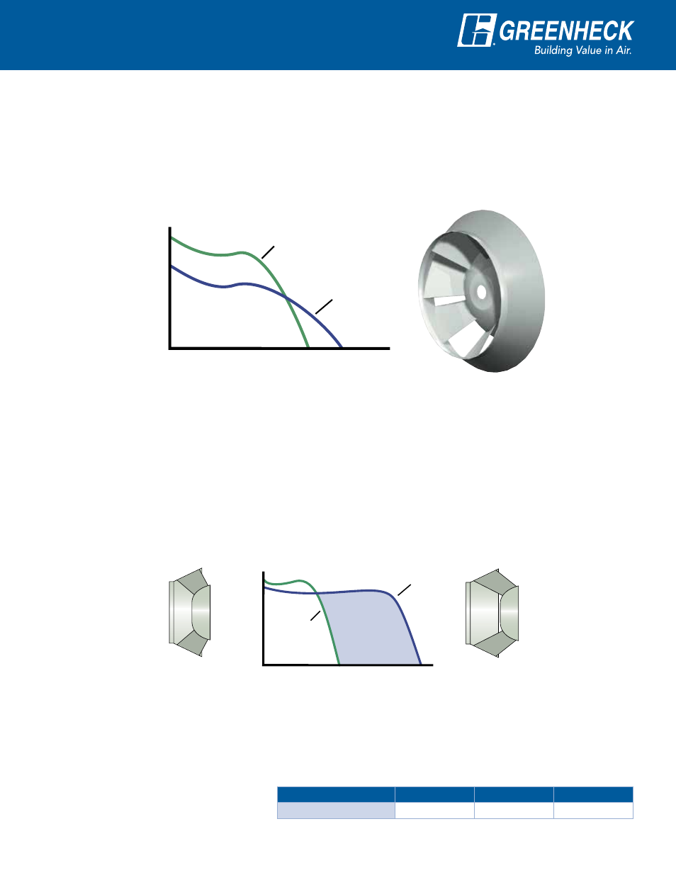
Belt Drive: Fan Class
Class I and II fans have different wheel designs with different performance characteristics.
Class I mixed flow wheels are optimized for performances involving low pressures and high volumes. Class II
wheels are designed for a steeper fan curve with higher pressure capabilities. This is illustrated in the graph
with the two different class wheels plotted at identical fan RPMs.
When selecting a mixed flow fan, it cannot be assumed that moving into a Class II fan will produce the same
results as a Class I mixed flow fans. Model QEI-L utilizes a Class I wheel.
Direct Drive: Percent Wheel Width
Direct drive mixed flow fans are optimized for performance requirements by the use of partial width wheels. This
is necessary because the fan RPM is commonly fixed and identical to the motor RPM. A reduction in the width
of the wheel (or the air passage) results in reduced airflow capacity and a steeper fan curve. This is similar to
the effect of a reduced pitch in a direct drive vane axial fan. QEID wheels are available in 5% increments from
50 - 100% wheel width.
QEID fans can be used in conjunction with variable frequency drives (VFD’s) for variable air volume (VAV)
systems. In these applications, the wheel width is optimized to ensure efficient operation and stable
performance throughout the turndown range. VFD’s are also used for final system balancing and to reduce the
airflow when building requirements are reduced. In this case, the fan and wheel width are selected using the
final design CFM and static pressure.
Sound Power versus Sound Pressure
The sound values displayed on the performance pages are in terms of inlet sound power (
L
W
i
A) and outlet sound
power (L
W
o
A
). These values are the acoustic power radiating from the inlet and outlet of the fan, respectively.
Sound pressure, expressed as dBA, is the acoustic pressure at a point in space which can be measured with a
microphone or can be heard. To convert sound power (L
w
A) into sound pressure (dBA), the following corrections
are applied for a hemispherical free field.
dBA = L
w
A - correction
Distance from Fan
3 ft. (0.9 m)
5 ft. (1.5 m)
10 ft. (3.0 m)
Correction
7 db
11.5 db
17.5 db
Note: Refer to AMCA Publication 303, Application of Sound Power Level Ratings for additional information on calculating typical sound pressure levels for fan installation.