Components introduction, En g lis h, 1 casing’s internal structure – GIGABYTE 230 User Manual
Page 4
4
En
g
lis
h
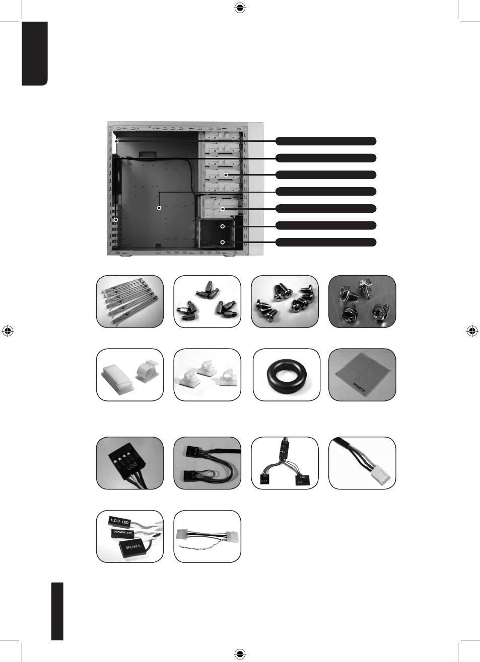
1.Components Introduction
1-1 Casing’s Internal Structure
Accessory Box
Front Cable Kit
Power Supply
Securing Screw x 4
Dust Remover
Cloth
USB 2.0
IEEE1394
(Multi-connectors)
Power Supply Bay
PCI Tool-Free Fastener
Motherboard tray
5.25” Front Device Bay
3.5” Internal Device Bay
Accessory Box
(Refer to the figures below for the attachments in the accessory box)
(Refer to the figures below for the cable connectors)
Audio Set
(HD & AC’97)
3-Pin Fan Connector
Power SW / HDD LED
/ Speaker Connector
Copper Stand Off
x 9
Securing Runner x 6
Motherboard
Securing Screw x 9
Large Wire Clamp
x 2
Magnet Ring x 1
Mini Wire Clamp
x 3
3.5” Front Device Bay
4-Pin Power LED
Connector
See also other documents in the category GIGABYTE Hardware:
- GA-8I915GM (80 pages)
- AGP 4X(1.5V) (112 pages)
- GA-M68MT-D3P (40 pages)
- Xeon Processor Motherboard GA-5YXS1-RH (54 pages)
- GA-MA770T-UD3P (100 pages)
- GA-K8VM800M (96 pages)
- GN-AP101B (39 pages)
- GA-P31-ES3G (84 pages)
- GA-K8NS ULTRA-939 (96 pages)
- GA-8I865GME-775-RH (64 pages)
- GA-EP45-UD3L (112 pages)
- GA-8I915MD-GV (80 pages)
- GA-8S661FXM-775 (88 pages)
- GN-B41G (84 pages)
- LGA775 Socket Motherboard for Intel GA-73PVM-S2H (100 pages)
- GA-965GM-S2 (88 pages)
- GeForceTM 6600 Graphics Accelerator GV-N66128DP (34 pages)
- GN-FE605(M) (38 pages)
- GN-FE605(M) (62 pages)
- 4635 (26 pages)
- GA-8VM800M-775 (88 pages)
- AMD Socket 939 Processor Motherboard GA-K8N51PVM9-RH (96 pages)
- GA-8ANXP-D (88 pages)
- 5230 (97 pages)
- 7VM333M-RZ (36 pages)
- AMD Socket 754 Processor Motherboard GA-K8NE-RH (80 pages)
- Pentium 4/D Processor Motherboard GA-5EASV-RH (88 pages)
- GN-WPKG (26 pages)
- Intel Pentium 4 Processor Motherboard GA-8VM800M (80 pages)
- 8S648FXP-RZ (40 pages)
- AirCruiser G GN-WB01GS (26 pages)
- PHASER 4500 (128 pages)
- GV-R487D5-1GD (34 pages)
- GA-8IP775 Series (80 pages)
- GN-A11G (57 pages)
- GA-K8VT800 (80 pages)
- GA-8I945PLGE-RH (80 pages)
- SmartSetup 3 (4 pages)
- GA-K8U-939 (88 pages)
- GA-K8NE (80 pages)
- GA-M61PME-S2P (88 pages)
- 7VM400M-RZ (36 pages)
- GA-K8NF-9 (88 pages)
- Pentium II / III Processors 6ZMM (23 pages)