4 gasoline fuel system, Danger, 2 testing the installation – Guardian Technologies 004702-0 User Manual
Page 28: Figure 6.9 – airflow through engine/generator, Figure 6.8 — compartment floor cutout, 26 generac, Power systems, inc
26 Generac
®
Power Systems, Inc.
Figure 6.9 – Airflow Through Engine/Generator
6.3.2 TESTING THE INSTALLATION
Generac recommends testing the installation to be
sure adequate cooling airflow is available to the unit
before placing the unit into service. If the unit shows
signs of overheating, enlarge the air openings. Never
place a unit into service until absolutely certain that
cooling and ventilation is adequate.
NOTE:
The installation must be tested, especially if bring-
ing in air from below the generator set.
6.4 GASOLINE
FUEL
SYSTEM
Gasoline is highly flammable, and its vapors are
explosive. Comply with all codes, standards and
regulations pertaining to gasoline fuel systems
used in recreational vehicle generators.
Properly install and maintain the fuel system
and keep it entirely free of leaks. Gasoline
vapors must not enter the vehicle interior.
The installation of a gasoline fuel system (Figure
6.10) for a recreational vehicle generator set must
comply with applicable codes, standards and regula-
tions. The entire fuel system must be completely free
of leaks. There must be no possibility of gasoline
vapors entering the vehicle interior.
DANGER
◆
Section 6 – Installation
QUIETPACT 55, 65, and 75 Recreational Vehicle Generators
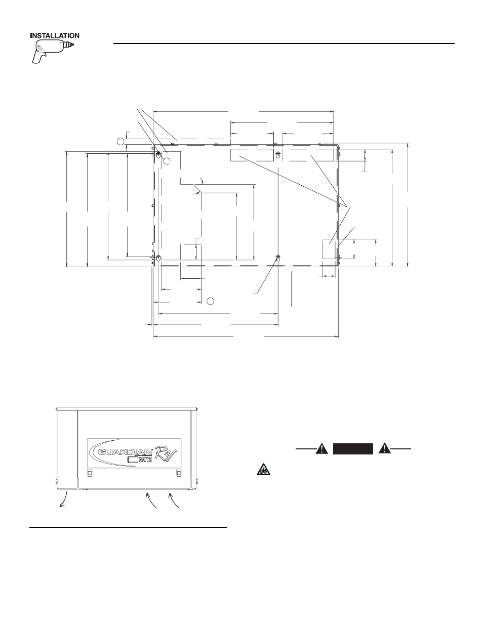
Figure 6.8 — Compartment Floor Cutout
A
B
545
[ 21 7/16"]
TYP.
95.6
[ 3 3/4"]
183.6
[ 7 1/4"]
821.2
[ 32 5/16"]
233.2
[ 9 3/16"]
469
[ 18 7/16"]
195.8
[ 7 11/16"]
57
[ 2 1/4"]
TYP.
516.2
[ 20 5/16"]
TYP.
469.8
[ 18 1/2"]
495
[ 19 1/2"]
526.2
[ 20 11/16"]
70.8
[ 2 13/16"]
344.6
[ 13 9/16"]
45
°
305.9
[ 12 1/16"]
536.2
[ 21 1/8"]
TYP.
54
[ 2 1/8"]
126.2
[ 5"]
90
[ 3 9/16"]
REF.
564.1
[ 22 3/16"]
AIR INTAKE
HOT AIR
EXHAUST
3/8"-16 WELDNUTS
(8 PLACES)
FRONT
TAILPIPE
LOCATION
FUEL INLET
25.4
[ 1"]
TYP.
6.7
[ 1/4"]
842.4
[ 33 3/16"]
VIEW FROM TOP
NOTE: ALL AIR INTAKES AND EXHAUST OUTLETS MUST BE
KEPT CLEAR OF ANY OBSTRUCTIONS. ALL OPEN AREA
IS REQUIRED FOR COOLING.
568
[ 22 3/8"]
219.8
[ 8 5/8"]