Graco 258906 User Manual
Page 13
Motor Control Board
3A0246C
13
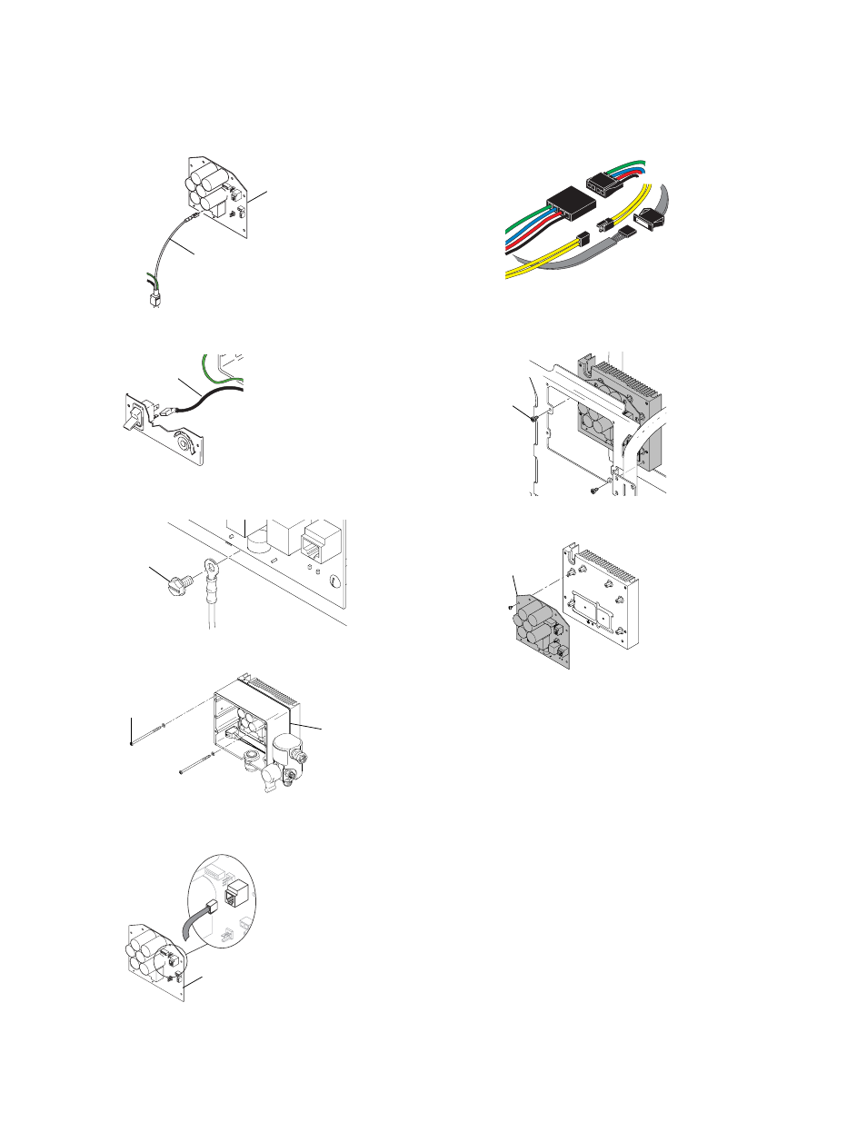
11. Disconnect white power cord conductor (D) from
motor control board (24).
12. Disconnect black power lead (J) on motor control
board (24) from ON/OFF switch.
13. Remove ground screw (58) from motor control
board/heat sink assembly.
14. Remove two top screws (61) and control box (3).
15. Disconnect transducer connector from motor control
board (24).
16. Disconnect three motor connectors from motor con-
trol board to motor.
17. Remove two screws (83) holding motor control
board /heat sink assembly to power module frame.
Remove motor control board/heat sink assembly.
18. Remove six outer screws, two inner screws, and
remove control board (24) from heat sink.
ti15851a
24
D
ti15849a
J
ti15846a
58
ti15912a
3
61
ti12999a
24
ti15847a
ti15845a
83
ti15844a
24