Installation (continued), Electrical connections, Typical control center components – Greenheck Fan HRE-20 User Manual
Page 5
5
Main
Disconnect
On
Off
Exhaust
Hood
Control Center
Intake
Hood
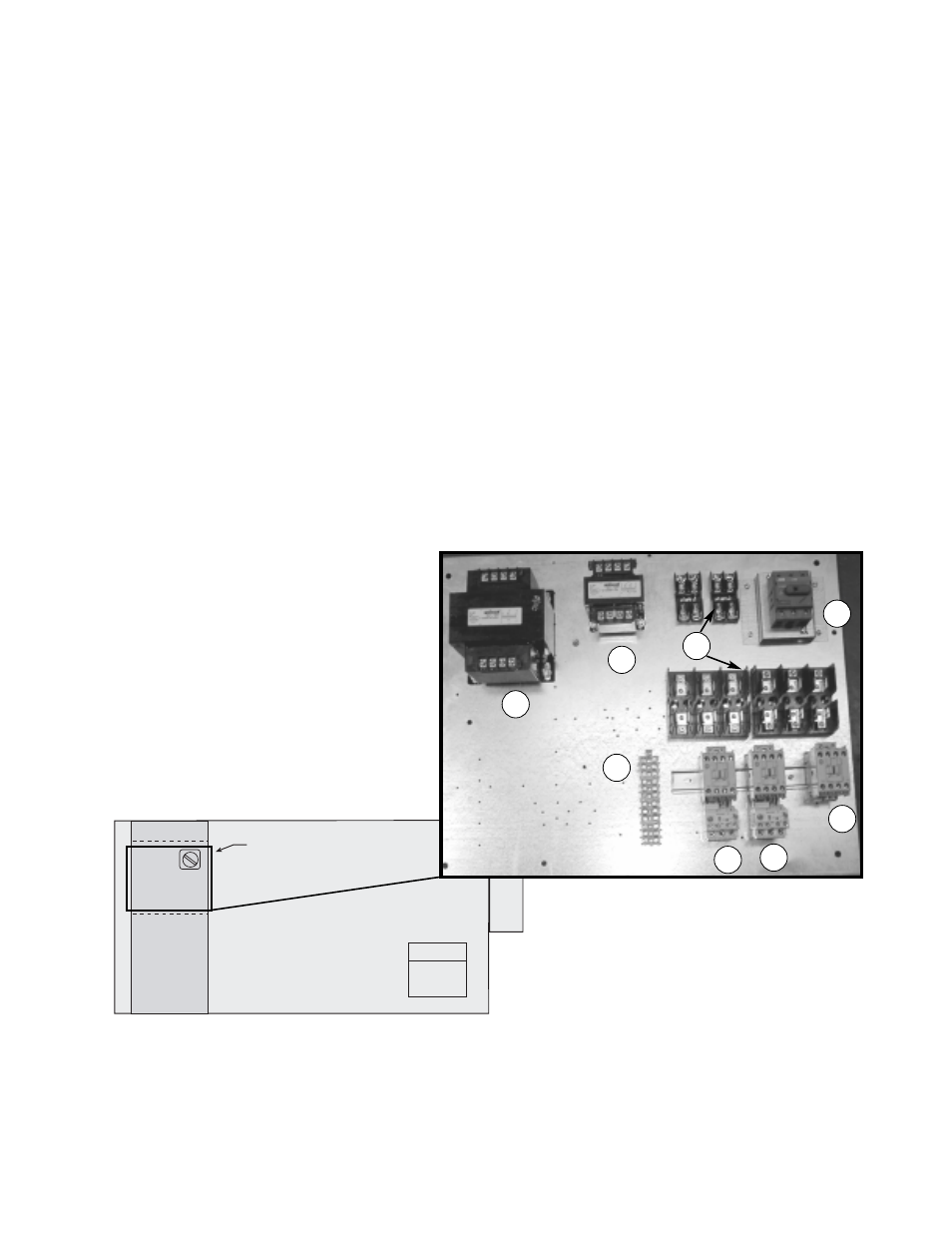
INSTALLATION (continued)
ELECTRICAL CONNECTIONS
The electrical supply must be compatible with that shown on the nameplate: voltage, phase, and amperage
capacity. The electrical supply line must be properly fused and conform to local and national electrical codes.
All internal electrical components are pre-wired at the factory. Field electrical connections only need to be made
inside the unit to the main disconnect (See FIGURE 5, Item #1) and the 24 volt control circuit (See FIGURE 5,
Item #7). A door interlocking safety disconnect is provided as standard feature.
Note:
Standard factory installed electric post heaters have their own disconnect separate from the unit
disconnect. Thus, electric post heaters require a separate power connection.
IMPORTANT:
Use minimum 14 ga. wire for 24 volt control power.
Control wire resistance should not exceed 0.75 ohms (approximately 285 feet total length for
14 ga. wire; 455 feet total length for 12 ga. wire). If wire resistance exceeds 0.75 ohms, an
industrial-style, plug-in relay should be added to the unit control center and wired in place of
the remote switch (between terminal blocks 2 and 3 on the control strip — See FIGURE 5,
Item #7). The relay must be rated for at least 5 amps and have a 24 Vac coil. Failure to
comply with these guidelines may cause motor starters to “chatter” or not pull in which can
cause contactor failures and/or motor failures.
1
2
3
4
6
5
7
8
1. Main Disconnect
2. Motor Starter — Exhaust/Scavenger
Air Fan
3. Motor Starter — Outdoor Air Fan
4. Motor Contactor — Energy Wheel
5. Control Power Transformer
(24 VAC Secondary)
6. Energy Wheel Motor Transformer
(230 VAC Secondary)
(for HRE-20 & HRE-45 units with
primary voltage greater than 230 Vac)
7. 24 VAC Terminal strip
8. Fuses for the control circuit, wheel
drive transformer, and blower
motors.
TYPICAL CONTROL CENTER COMPONENTS
FIGURE 5