Graco BULLDOG 222248 User Manual
Page 9
9
306–646
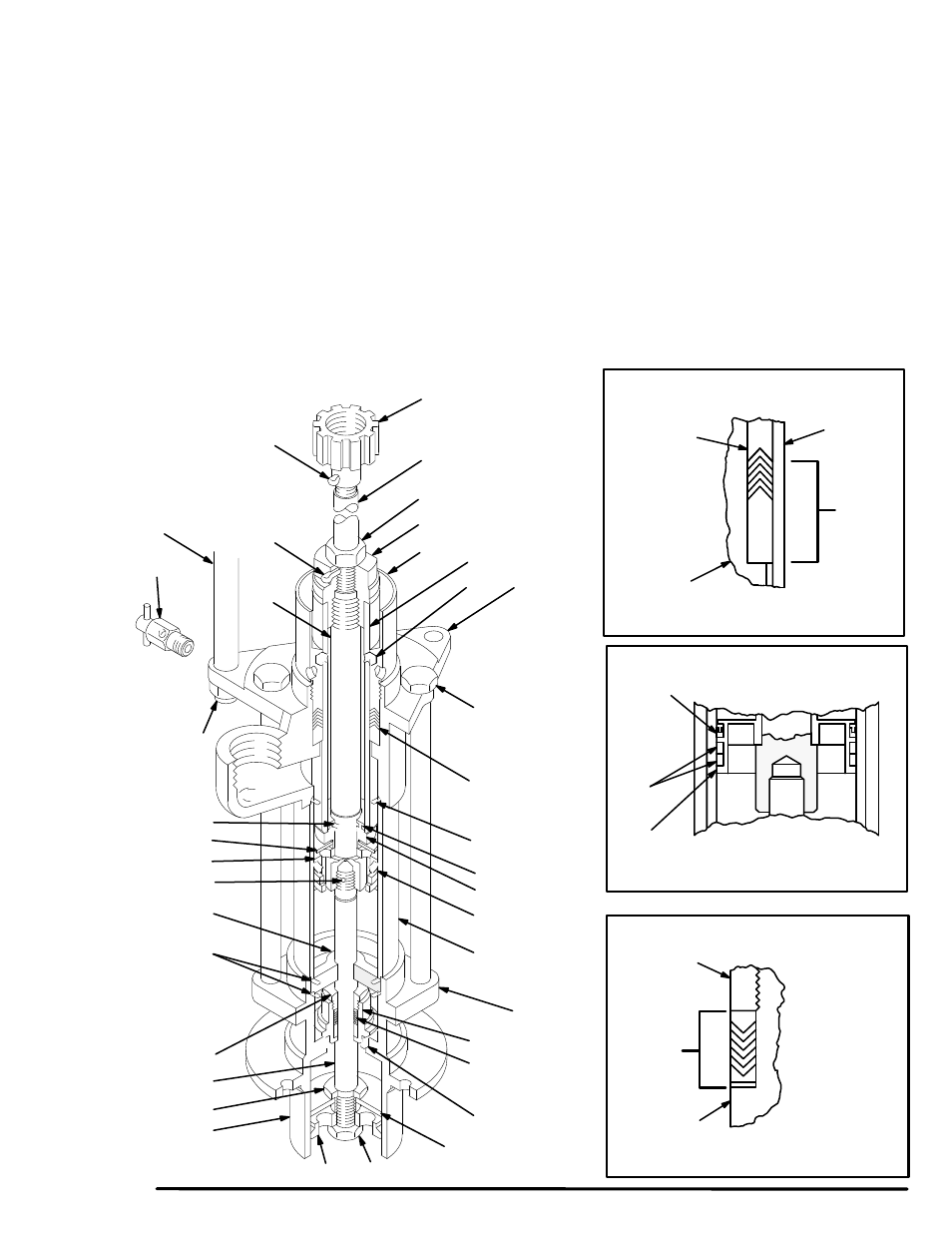
9. Carefully guide the intake valve housing (28) up over
the priming rod (32) and install it on the cylinder (39).
Insert the four tie bolts (8) through the outlet housing
(26) and engage the holes in the intake valve hous-
ing. Torque the tie bolts oppositely and evenly to 60
ft–lb (82 N.m).
10. Install the plate guide (31), plate (36), priming piston
(37) and nut (6) on the priming rod (32). If necessary,
push down on the displacement rod (18) to provide
sufficient clearance from the intake valve housing
(28).
11. Tighten the packing nut/wet–cup (21) just enough to
prevent leakage – no tighter.
12. Check the alignment of the displacement rod (18) by
inserting a size E (0.254 in. diameter) drill shank be-
tween the packing nut/wet–cup (21) and the rod. If
the drill shank cannot be passed freely around the
rod, tighten the tie bolt (8) on the side which is bind-
ing.
13. Screw the connecting rod (53) into the upper cap
(33). Insert the cotter pin (42) and tighten the locknut
(45).
14. Align the pump outlet on the outlet housing (26) with
the optional outlet at the base of the air motor (1).
Loosely screw the tie rod locknuts (44) onto the tie
rods (52). Lubricate the o–ring (47) and the top
thread of the connecting rod (53). TIghten the cou-
pling nut (50) to attach the displacement pump to the
motor. Insert the cotter pin (41).
15. Start the pump and run it slowly to check for binding.
Adjust the tie rods as necessary , then torque the
locknuts (44) to 40–50 ft–lb (54–68 N.m).
16. Reconnect the fluid and air lines. Reconnect the
ground wire if it was disconnected during service.
Fig 2
50
53
45
42
20
21
52
26
SEE DETAIL A
19
34
SEE DETAIL B
38
SEE DETAIL C
3
30
6
36
37
28
31
32
11
28
*27
29
7
39
*15
4
33
41
8
TORQUE TO
60 ft–lb
(82 N.m)
17*
DISPLACEMENT PUMP 204–641
DETAIL C
DETAIL B
DETAIL A
44
TORQUE TO
40–50 ft–lb
(54–68 N.m)
21
REF
26
REF
LIPS OF
V–PACKINGS
MUST
FACE
DOWN
LIPS OF
V–PACKINGS
MUST
FACE UP
LIPS OF
PACKING
MUST
FACE UP
11
REF
3
REF
*56
*35
38
REF
18
27*
REF. NO. 2
DISPLACEMENT
PUMP INCLUDES
ITEMS 3–39, 56–66
18
REF
64*
THROAT
GLAND/
PACKING
STACK
*65
INTAKE
VALVE
GLAND/
PACKING
STACK
66