Garmin GHP 10 User Manual
Page 6
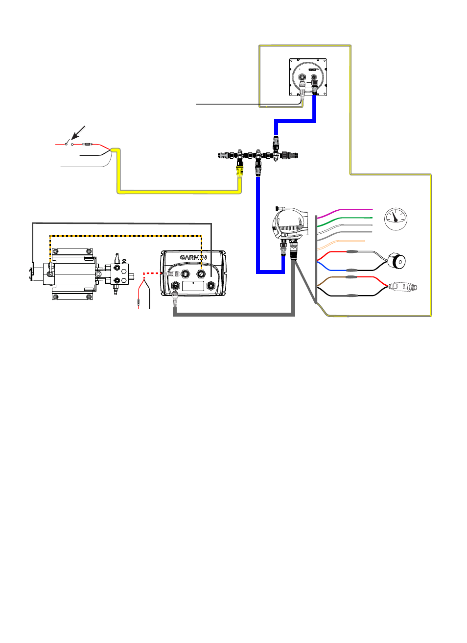
GHP 10 Marine Autopilot System Installation Instructions
ENCODER
CCU
POWER
}
PUMP
GHP 10 General Wiring outline
NMEA 000 network (see
)
CCU
ECU
Pump
(compact .1 L pictured)
GHC 10
Shadow Drive
Alarm buzzer
Boat tachometer
Yellow CCU signal wire (see
)
For CCU bare-wire connections, see
.
For tachometer wiring,
see
Orange - unconnected
Red (+) White (+)
Red (+)
Blue (-) Black (-)
Black (-)
Black (-)
Brown (+)
Red (+)
Black (-)
1 Vdc*-0 A fuse.
for
cable size and length
requirements.
NMEA 000 power cable
9–1 Vdc
A fuse
Red (+)
Black (-)
Drain (-)
Ignition or
in-line switch
Yellow CCU signal wire
(see
CCU/ECU Interconnect cable
Black (-)
CCU ground
notes:
This diagram is for planning purposes only. Specific wiring diagrams are included in the detailed installation instructions for
each component. Hydraulic connections are not shown in this diagram.
If your boat uses an electrical system that provides more than 12 Vdc, or if you sporadically receive tachometer errors, install an
external tachometer filter (010-11399-00). Contact your local Garmin dealer or Garmin product support for more information.
Connect an optional NMEA 0183-compatible GPS device to the data cable on the GHC 10. See
for more information.
Connect an optional NMEA 2000-compatible GPS device to the NMEA 2000 network. See
•
•
•
•
* Newer ECU units are compatible with 24 Vdc systems. See
for more information.
* Newer ECU units are compatible with 24 Vdc systems. See
for more information.