Basic bending operations, Clamp adjustment – Grizzly Bending Brake T21319 User Manual
Page 2
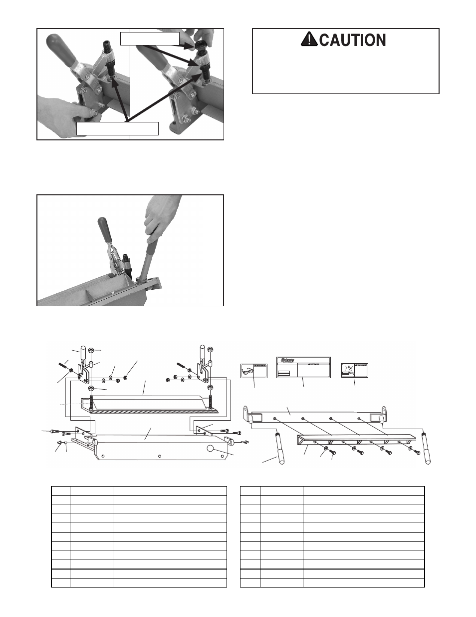
4. screw the two breaker bar levers into the
breaker bar holes, as shown in
Figure 5.
basic bending operations
1. open the bending brake and place the work-
piece beneath the clamping angle.
2. Close the clamp assemblies until they lock.
if the workpiece is to thick or too thin for
the clamps, adjust the clamps according to
clamp adjustment on this page.
3. When the workpiece is secured in the bend-
ing brake, lift the breaker bar levers to form
the desired angle.
clamp adjustment
1. Without turning the clamping set screw, turn
the adjusting nuts clockwise to adjust for
thicker workpieces and counterclockwise to
adjust for thinner workpieces. Adjust each
clamp an equal amount.
Figure 5. Breaker bar lever installation.
t21319 breakdown and parts list
PINCH
HAZARD!
Keep hands away
from clamp area
when clamping or
bending.
EYE INJURY
HAZARD!
Always wear safety
glasses when using
this machine.
MODEL H2788
24" BENDING BRAKE
Specifications
Max. Workpiece Thickness: 18 Ga.
Max. Bend: 145°
Max. Workpiece Width: 27-1/2"
Weight: 60 lbs.
To reduce the risk of serious personal injury when using this
machine:
1. Read and understand the manual before starting.
2. Always wear eye protection.
3. Wear heavy leather gloves when handling sheet metal.
4. Do not exceed the rated capacity of this machine.
5. Do not use a breaker bar to gain leverage.
6. Always firmly clamp workpiece before bending.
1
3
7
5
2
6
5
10
11
3
8
4
14 13
15
16
21
22
23
24
17
18 20 19
REF PART #
DESCRIPTION
REF PART #
DESCRIPTION
1
PT21319001 CLAMP
14
PT21319014 FLANGE BEARING
2
PSS39M
SET SCREW M10-1.5 X 50
15
PT21319015 BASE
3
PN05M
HEX NUT M16-1.5
16
PT21319016 BREAKER BAR
4
PB01M
HEX BOLT M10-1.5 X 30
17
PT21319017 THREADED LEVER M20-1.75
5
PN02M
HEX NUT M10-1.5
18
PT21319018 BREAKER ANGLE
6
PLW06M
LOCK WASHER 10MM
19
PB03M
HEX BOLT M8-1.25 X 16
7
PT21319007 COLLAR
20
PW01M
FLAT WASHER 8MM
8
PT21319008 SPECIAL SET SCREW M10-1.5 X 90
21
PT21319021 PINCH HAZARD WARNING
10
PT21319010 CLAMPING ANGLE
22
PT21319022 MACHINE ID LABEL
11
PT21319011 CLAMP MOUNTING PLATE
23
PLABEL-11D SAFETY GLASSES LABEL
13
PT21319013 PIVOT PIN 16 X 50
24
PPAINT-1
GREEN TOUCH-UP PAINT
Figure 4. Clamp installation.
Adjusting nuts
Clamping set screw
the bending brake must be clamped or
secured to a workbench before being used.
Failure to do so can lead to personal injury
or machine damage!