Warning – GSW 73992 User Manual
Page 6
- 6 -
• Must be installed to allow complete drainage of both the
valve and discharge line.
• Must not discharge so as to come in contact with any
electrical part or wiring.
Under no circumstances is the manufacturer to be held
responsible for any water damage in connection with
this water heater.
WARNING!
Closets without drains and carpeted areas are examples of
unsuitable locations for any water heater. Select a location
as centralized within the piping system as possible. The
heater should be located in an area not subject to freezing
temperatures. If this heater is to be installed directly on car-
peting, the carpeting must be protected by a metal or wood
panel beneath the heater, extending beyond the full width
and depth of the heater by a minimum 80mm (3 in.). If the
heater is installed in a closet or alcove, the entire floor must
be covered by the panel. This panel must be strong enough
to support the weight of the heater full of water without
breaking. Failure to heed this warning may result in a fire
hazard.
Closed System/Thermal Expansion
During the heating cycle of the water heater, the water
expands causing pressure inside the water heater to
increase. The water utility supply meter may contain a
check valve. This will create a closed water system. If the
pressure in a closed water system exceeds 1034kPa (150
PSI), water will discharge from the temperature and pres-
sure (T&P) relief valve. This is the normal safety function of
a relief valve and indicates the proper functioning of the
valve. Only if the discharge from the relief valve is continu-
ous or for an extended period of time does this indicate a
malfunction of some sort. Should this occur, have the oper-
ation of the heater checked by a technician qualified to do
so. Frequent operation of the T&P valve can result in a build
up of natural mineral deposits on the valve seat, rendering
the valve inoperative. Should this happen, the valve needs
to be replaced. To prevent this from happening install a
diaphragm-type expansion tank, that is suitable for potable
water, on the cold water supply line. The expansion tank
must have a minimum capacity of 6 litres (1.5 USG.) for
every 190 litres (50 USG) of stored water and be rated for
1034kPa (150 PSI) or the working pressure of the water
heater. NEVER PLUG OR REMOVE the T&P valve.
Important:
Do not plug or remove the temperature
and pressure relief valve.
Unpacking the Water Heater
Important:
Do not remove any permanent instructions,
labels, or the data label from the outside of the water heater
or on the inside of panels. Remove exterior packaging and
place installation components aside. Inspect all parts for
damage prior to installation and start-up. Completely read
and understand all instructions before attempting to assem-
ble and install this product. After installation, dispose of
packaging material in the proper manner.
Important:
Strictly follow the installation instructions
before making electrical connections.
Piping Installation
Piping, fittings, and valves should be installed according to
the installation drawing (Figure 4). If the indoor installation
area is subject to freezing temperatures, the water piping
must be protected by insulation. Water supply pressure
should not exceed 80% of the working pressure stated on
the water heater’s data plate. If the supply pressure is high-
er than this limit, a pressure limiting valve with a bypass
must be installed in the cold water inlet line. This should be
placed on the supply to the entire building in order to main-
tain equal hot and cold water pressures.
Excessive Weight Hazard
Use two or more people to move and install
water heater.
Failure to do so can result in back or other
injury.
WARNING
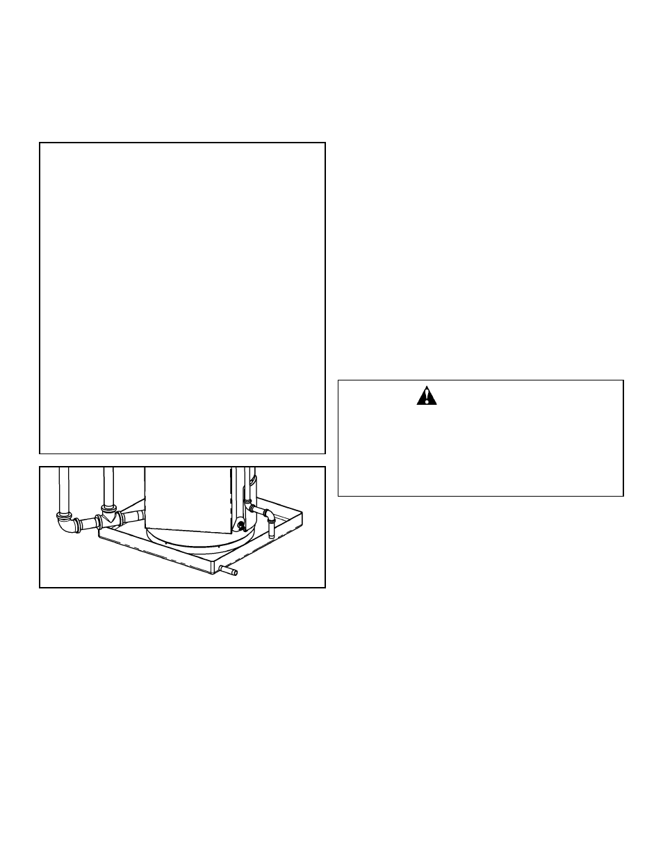
FIGURE 3: Drain Pan
IMPORTANT:
This water heater must be installed strictly in accordance
with the instructions enclosed, and local electrical, fuel
and building codes. It is possible that connections to the
water heater, or the water heater itself, may develop
leaks. IT IS THEREFORE IMPERATIVE that the water
heater be installed so that any leakage of the tank or relat-
ed water piping is directed to an adequate drain in such a
manner that it cannot damage the building, furniture, floor
covering, adjacent areas, lower floors of the structure or
other property subject to water damage. This is particular-
ly important if the water heater is installed in a multi-story
building, on finished flooring or carpeted surfaces. GSW
WILL NOT ASSUME ANY LIABILITY for damage caused
by water leaking from the water heater, pressure relief
valve, or related fittings. Select a location as centralized
within the piping system as possible. In any location
selected, it is recommended that a suitable drain pan be
installed under the water heater. This pan must limit the
water level to a MAXIMUM depth of 45mm (1 3/4 in.) and
have a diameter that is a minimum of 50mm (2 in.) greater
than the diameter of the water heater. Suitable piping shall
connect the drain pan to a properly operating floor drain.