True to the music, 1/4” trs - tip send / ring return, G 2 3 – Radial Engineering WORKHORSE 500 SERIES User Manual
Page 9: G 4 5, G 6 7, G 8 13
True to the Music
Radial Engineering Ltd.
Workhorse User Guide
6
Expansion Buss
The Workhorse stereo expansion buss is designed to allow multiple
Workhorses to be used together to create larger mixing systems. This
also lets you create ‘sub-zones’ and ‘group’ mixes. Standard unbalanced
¼” cables are used to connect between units with choice of input or output
depending on which Workhorse will be set as the ‘master’ and which will be
designated as the ‘slave’. All you do to link one to the other is connect two
cables (left and right). The output from the ‘slave’ will now feed the input on
the ‘master’ essentially combining the two to create a 16x2 mixer.
EXPANSION
BUSS
IN
OUT
LEFT
RIGHT
IN
OUT
EXPANSION
BUSS
IN
OUT
LEFT
RIGHT
IN
OUT
Workhorse 1
Slave
Workhorse 2
Master
You can take things a step or two further by adding more Workhorses with
the each subsequent unit delivering more and more channels. This could
for instance be used in a live scenario where channels 1~8 from the fi rst
Workhorse are vocals with the output being treated like a sub-group sent
to a wedge monitor system while the full mix from the master (1~16 or
1~24 channels) is sent to the PA and recording system.
-
+
G
-
+
G
-
+
G
1
2
3
4
5
ON
ON
MONO
2
3
4
1
LEVEL
CLIP
PAN
Made in Canada
LEVEL
ON
6
7
8
5
LEVEL
MAIN
MON
48V PHANTOM
+16V / -16V
LEVEL
CLIP
PAN
ON
LEVEL
CLIP
PAN
ON
LEVEL
CLIP
PAN
PAN
PAN
PAN
PAN
ON
LEVEL
CLIP
LEVEL
ON
LEVEL
CLIP
ON
LEVEL
CLIP
ON
LEVEL
CLIP
ON
-
+
G
-
+
G
-
+
G
1
2
3
4
5
ON
ON
MONO
2
3
4
1
LEVEL
CLIP
PAN
Made in Canada
LEVEL
ON
6
7
8
5
LEVEL
MAIN
MON
48V PHANTOM
+16V / -16V
LEVEL
CLIP
PAN
ON
LEVEL
CLIP
PAN
ON
LEVEL
CLIP
PAN
PAN
PAN
PAN
PAN
ON
LEVEL
CLIP
LEVEL
ON
LEVEL
CLIP
ON
LEVEL
CLIP
ON
LEVEL
CLIP
ON
-
+
G
-
+
G
-
+
G
1
2
3
4
5
ON
ON
MONO
2
3
4
1
LEVEL
CLIP
PAN
Made in Canada
LEVEL
ON
6
7
8
5
LEVEL
MAIN
MON
48V PHANTOM
+16V / -16V
LEVEL
CLIP
PAN
ON
LEVEL
CLIP
PAN
ON
LEVEL
CLIP
PAN
PAN
PAN
PAN
PAN
ON
LEVEL
CLIP
LEVEL
ON
LEVEL
CLIP
ON
LEVEL
CLIP
ON
LEVEL
CLIP
ON
Slave 1 - Channels 1 - 8
Slave 2 - Channels 1 - 16
Master - Channels 1 - 24
Expansion Buss
Expansion Buss
R
L
R
L
R
L
Keep in mind that the Workhorse’s modular fl exibility also enables you to
use the individual XLR or ¼” outputs from each module card slot to feed a
recorder should this be desired. Once you get to know the Workhorse the
creative options are almost endless!
Radial Tech Note: Expansion Buss
The Radial ‘open source’ approach also enables the expansion buss
to be interfaced with other manufacturer’s electronic equipment
that is equipped with similar functionality such as products made
by Rupert Neve Designs™. The expansion buss is essentially the
inverting (virtual earth) input of an op-amp in the mixer section of the
rack with a 4.75K Ohm resistor in series for unity gain connectivity.
This can be used by an external device so long as it can operate
into a 4.75K Ohm load. There is no DC blocking. This means that
if there is any DC on the output of the external device, the clipping
response of this stage will be non-symmetrical and headroom will
be reduced.
D-Sub Summing Mixer Input
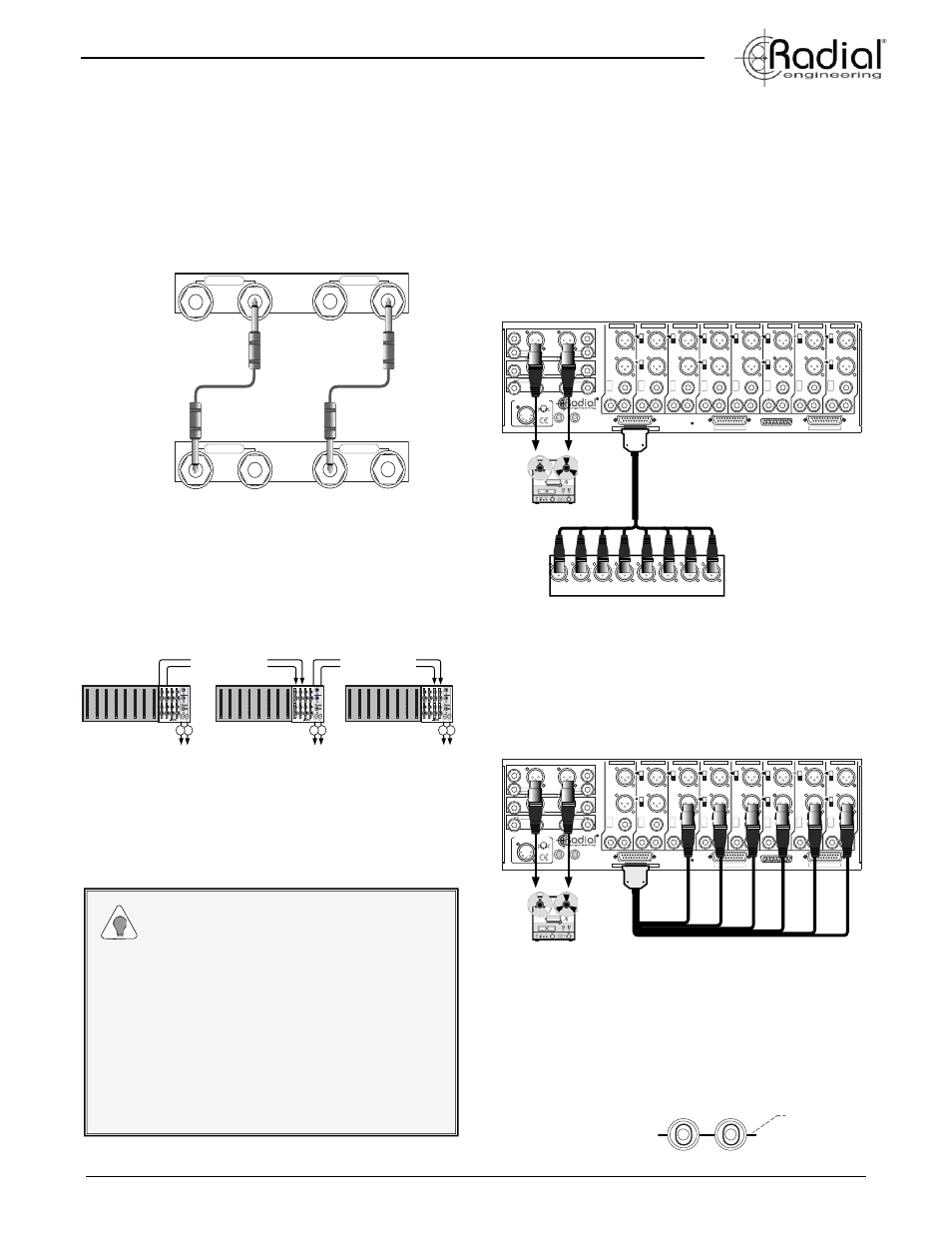
One of the cool extras built into the Workhorse is the ability to use it as
a stand-alone eight channel analog summing mixer. This feature also
enables older 500 series modules to be hard wired into the Workhorse
mix buss. A dedicated unbalanced 25-pin D-Sub input on the rear
panel provides access to the eight mixer inputs and accepts both
+4dB and -10dB line level sources.
For instance, if you prefer the sound of analog summing, and want
to mix eight channels from your ProTools™ rig, you simply connect
the output of your recording interface to the Workhorse summing
mixer D-Sub input and you can now mix using the eight front panel
level and pan controls.
PROTOOLS INTERFACE
+
INPUT
OMNIPORT
FEED
LINK
1
2
3
4
5
6
OUTPUT
INPUT
7
8
SUMMING MIXER INPUTS 1 ~ 8
INPUT
FEED
LINK
INPUT
FEED
LINK
INPUT
FEED
LINK
INPUT
FEED
INPUT
FEED
INPUT
FEED
INPUT
OUTPUT
LEFT
WORKHORSE RACK & MIXER
RIGHT
LEFT
RIGHT
EXPANSION
BUSS
GROUND
CHASSIS
CIRCUIT
DIRECT OUT 1 ~ 8
INPUTS 1 ~ 8
OFF
OFF
CARD SLOT 1
CARD SLOT 3
CARD SLOT 5
CARD SLOT 7
CARD SLOT 2
CARD SLOT 4
CARD SLOT 6
CARD SLOT 8
OMNIPORT
OMNIPORT
OMNIPORT
OMNIPORT
OMNIPORT
OMNIPORT
OMNIPORT
Made in Canada
Radial Engineering Ltd.
1/4” TRS - TIP SEND / RING RETURN
INSERT
INSERT
MAIN
OUT
MON
OUT
OFF
OFF
OFF
OFF
OFF
OFF
OFF
OFF
OFF
OUTPUT
OUTPUT
OUTPUT
OUTPUT
OUTPUT
OUTPUT
OUTPUT
OUTPUT
INPUT
OUTPUT
INPUT
OUTPUT
INPUT
OUTPUT
INPUT
OUTPUT
INPUT
OUTPUT
INPUT
OUTPUT
INPUT
PIN DIAGRAM - PANEL VIEW
1
-
+
G
-
+
G
2
3
-
+
G
-
+
G
4
5
-
G
-
+
G
6
7
-
+
G
-
+
G
8
13
IN
OUT
LEFT
RIGHT
IN
OUT
SPLIT VOLTAGE POWER SUPPLY
1
2
3
4
5
+18VDC
COM
+48VDC
+18VDC
COM
POWER SUPPLY
OUTPUTS
INPUT
-
+
G
-
+
G
-
+
G
1
2
3
4
5
INPUT
-
+
G
-
+
G
-
+
G
1
2
3
4
5
INPUT
-
+
G
-
+
G
-
+
G
1
2
3
4
5
INPUT
-
+
G
-
+
G
-
+
G
1
2
3
4
5
INPUT
-
+
G
-
+
G
-
+
G
1
2
3
4
5
INPUT
-
+
G
-
+
G
-
+
G
1
2
3
4
5
INPUT
-
+
G
-
+
G
-
+
G
1
2
3
4
5
INPUT
-
+
G
-
+
G
-
+
G
1
2
3
4
5
Using The Summing Mixer Input To Mix Older Modules
If you have a bunch of older API™ preamps and want to mix their
outputs using the built-in mixer, simply connect the individual
card-slot outputs to the summing mixer input using a D-Sub cable
and you are all set. The modules output signal will appear at the
corresponding mixer channel.
+
INPUT
OMNIPORT
FEED
LINK
1
2
3
4
5
6
OUTPUT
INPUT
7
8
SUMMING MIXER INPUTS 1 ~ 8
INPUT
FEED
LINK
INPUT
FEED
LINK
INPUT
FEED
LINK
INPUT
FEED
INPUT
FEED
INPUT
FEED
INPUT
OUTPUT
LEFT
WORKHORSE RACK & MIXER
RIGHT
LEFT
RIGHT
EXPANSION
BUSS
GROUND
CHASSIS
CIRCUIT
DIRECT OUT 1 ~ 8
INPUTS 1 ~ 8
OFF
OFF
CARD SLOT 1
CARD SLOT 3
CARD SLOT 5
CARD SLOT 7
CARD SLOT 2
CARD SLOT 4
CARD SLOT 6
CARD SLOT 8
OMNIPORT
OMNIPORT
OMNIPORT
OMNIPORT
OMNIPORT
OMNIPORT
OMNIPORT
Made in Canada
Radial Engineering Ltd.
1/4” TRS - TIP SEND / RING RETURN
INSERT
INSERT
MAIN
OUT
MON
OUT
OFF
OFF
OFF
OFF
OFF
OFF
OFF
OFF
OFF
OUTPUT
OUTPUT
OUTPUT
OUTPUT
OUTPUT
OUTPUT
OUTPUT
OUTPUT
INPUT
OUTPUT
INPUT
OUTPUT
INPUT
OUTPUT
INPUT
OUTPUT
INPUT
OUTPUT
INPUT
OUTPUT
INPUT
PIN DIAGRAM - PANEL VIEW
1
-
+
G
-
+
G
2
3
-
+
G
-
+
G
4
5
-
G
-
+
G
6
7
-
+
G
-
+
G
8
13
IN
OUT
LEFT
RIGHT
IN
OUT
SPLIT VOLTAGE POWER SUPPLY
1
2
3
4
5
+18VDC
COM
+48VDC
+18VDC
COM
POWER SUPPLY
Grounding Posts
The connection between chassis and circuit (analog) ground is made
between the binding posts on the rear panel (factory set). Opening
this connection will separate these grounds in the Workhorse itself
so the only connection point between them is in the power supply.
Further separation is not allowed by electrical safety authorities. It
will only be in rare and unusual circumstances these grounds will
need to be separated.
GROUND
CHASSIS
CIRCUIT
Tie Bar
Factory Installed