Servicing instructions, Replacing parts, Control box – Stovax PR0731 User Manual
Page 21
appliance. Note the orientation of the injector on the pipe.
10.7 Reassemble in reverse order and check for gas leaks.
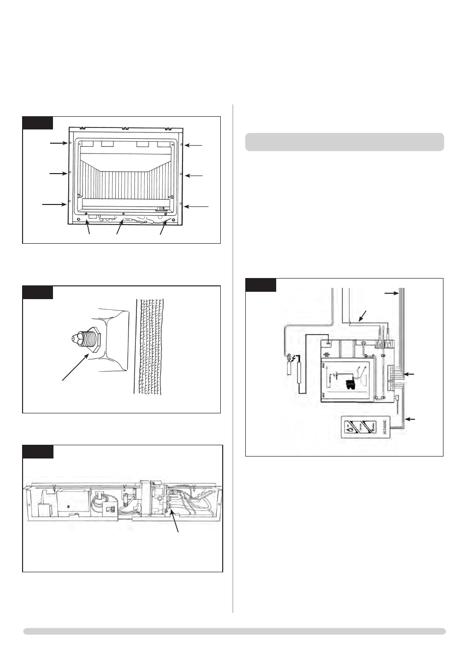
11. CONTROL BOX
11.1 Remove the lower panel, Diagram 6
11.2 Press on/off switch retaining clips in and pop put the switch.
Turn the switch to pass it through the retaining bracket.
11.3 Remove the two screws holding the control box to the
bracket. Slide the control box to the right and remove from
the bracket.
11.4 • Remove the two thermo current cables by removing
the two screws, Diagram 15
• Remove the eight loom wire from the control box,
Diagram 15
15
AR1915
Thermo current
cables
Eight wire cable
Touchpad
extension
cable
Battery
extension
cable
• Remove the battery extension cable, Diagram 15
• Remove the touch pad extension cable, Diagram 15
The control box can now be replaced.
11.5 After replacing the control box you may need to reprogram
the handset:
• Press and hold the reset button on the control box until
you hear two signals. After the second longer signal:
• Release the reset button and within 20
seconds
- Press the DOWN button on the handset until
you hear an additional long signal
confirming the new code
• Refer to Section 4 of the Installation Instructions to set
new code
21
SERVICING INSTRUCTIONS
REPLACING PARTS
12
AR1338
C
C
C
C
C
C
C
C
C
10.3 Remove the main burner as described in section 2.
10.4 Remove the locknut from the injector. See diagram 13
13
AR1345
10.5 Remove the feed pipe from the gas valve. See diagram 14.
14
AR1994
10.6 Remove the feed pipe with the injector attached from the