Installation, Cable connection, S t e p – FUJITSU ETERNUS DX80 User Manual
Page 2: Lan cables minisas cables (for drive enclosures), Power cords, Minisas cables (for host interface), Important
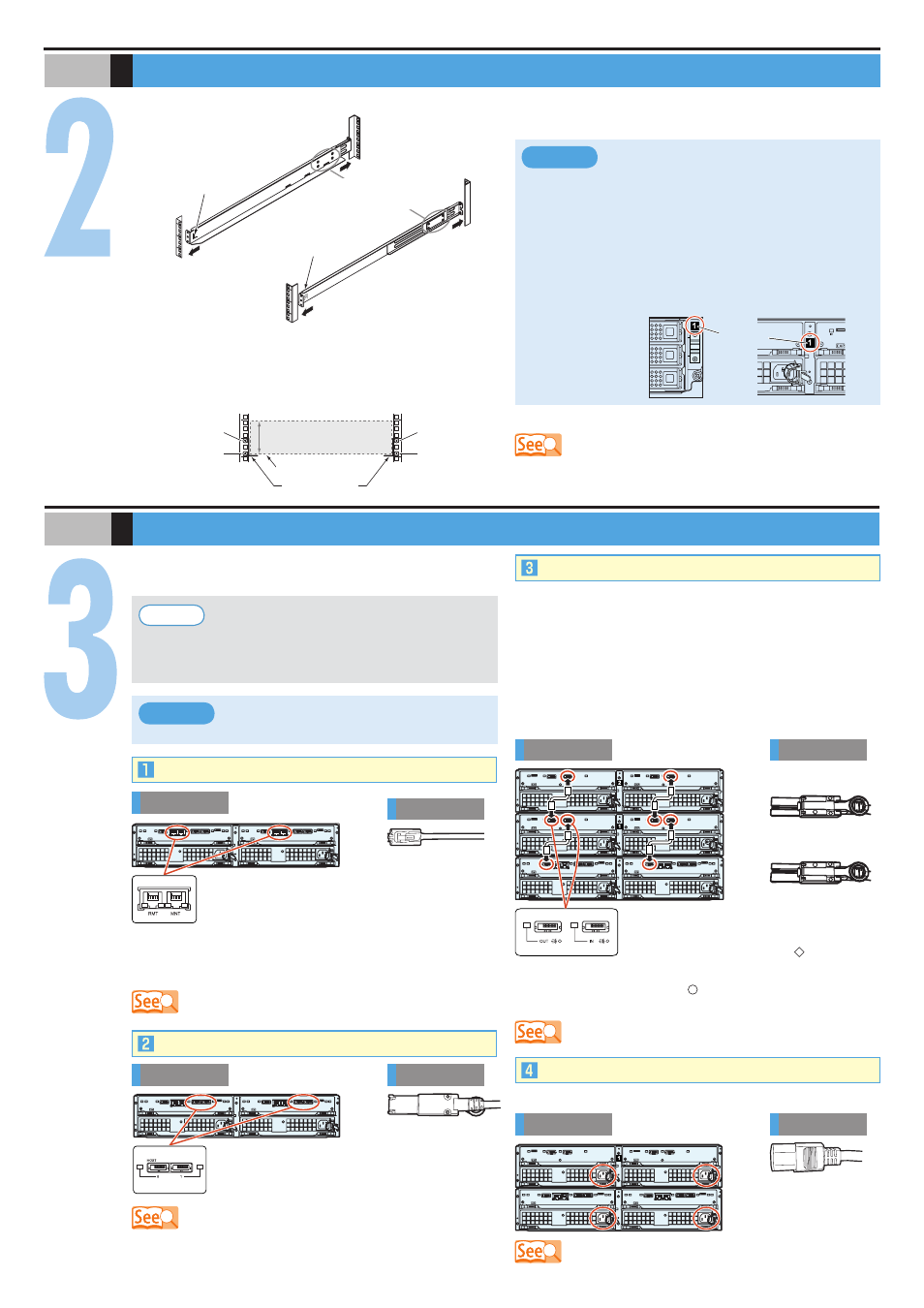
(Front rack pillars)
(Rear rack pillars)
"R" is stamped on the inner
side of the right rack rail.
"L" is stamped on the inner
side of the left rack rail.
Loosen the screws,
and adjust the rack rails to
the depth of the rack.
[Left]
[Right]
Adjust the rack rail (bracket)
size to fit the rack.
1.
S T E P
Installation
ETERNUS DX60/DX80
1st position
(M5 screws)
3rd position
(M5 screws)
1st position
(M5 screws)
3rd position
(M5 screws)
2U
[Screw location of the rack rail (bracket)]
Tighten the screws in the same locations on both the front and rear sides of the rack pillars
[Left]
[Right]
Rack rail (bracket)
Base line of the
ETERNUS DX60/DX80
Make sure to install or remove the enclosure
to or from the rack by two or more people.
Multiple Drive Enclosures must be connected
to the controller enclosure following the order
of the "DE_No. label" numbers attached to
each Drive Enclosure. The position of the
labels are in the positions shown below.
●
●
IMPORTANT
Between the EXP#0 and
EXP#1 expanders at the rear
of the drive enclosure
DE_No. label
At the right side of the front of
the drive enclosure
S T E P
Cable Connection
When Drive Enclosures are installed, miniSAS cables are
used to connect between the SAS ports of the enclosures.
Connect the Controller Enclosure to Drive Enclosure 1, Drive
Enclosure 1 to Drive Enclosure 2, Drive Enclosure 2 to Drive
Enclosure 3, etc. The number of Drive Enclosure can be
checked with the "DE_No." label.
Various cables need to be connected to the rear of the
ETERNUS DX60/DX80.
Rear view
Controller
Enclosure
Cable
LAN Cables
MiniSAS Cables (for Drive Enclosures)
Use release ties to hold the power cords in place.
Power Cords
Rear view
Controller
Enclosure
Drive
Enclosure
Cord
Rear view
Controller
Enclosure
Drive
Enclosure
Drive
Enclosure
Cable
MiniSAS Cables (for Host Interface)
Rear view
Controller
Enclosure
Cable
The SAS (OUT) port is on the left side, and
SAS (IN) port is on the right side.
Insert the connector with a mark on its
underside in the SAS (OUT) port.
Insert the connector with a mark on its underside in the
SAS (IN) port.
To help with cable management and prevent
incorrect connection, attach labels to the cables
and make a note of connection origins and
destinations.
Point
The cables should never be bent, twisted or
pulled.
IMPORTANT
Underside of
the SAS (OUT) side plug
Underside of
the SAS (IN) side plug
The RMT port is on the left side, and MNT port
is on the right side.
The MNT port must always be connected. The
RMT port only needs to be connected when the remote
support connection is to be independent of the customer
network.
For each CM, the port numbers are (left to right)
0 and 1. Connect a miniSAS cable to each of
these ports.
Example for connection of miniSAS cable
(when two Drive Enclosures are installed)
The rack rail (bracket) needs to be attached to the rack and the ETERNUS DX60/DX80 mounted.
Attach the rack rails (brackets) to the rack. The size of the
ETERNUS DX60/DX80 is 2U.
2.
Mount the ETERNUS DX60/DX80 in the rack.
3.
Fasten the ETERNUS DX60/DX80 to the rack.
4.
"5.2 Rack Installation" in the "User Guide"
"6.2 LAN Cable Connection (for Operation Management)" in the "User
Guide"
"6.5 MiniSAS Cable Connection (For SAS)" in the "User Guide"
"6.6 MiniSAS Cable Connection (For Drive Enclosures)" in the "User
Guide"
"6.7 Power Cord Connection" in the "User Guide"