FUJITSU FTP-604 FTP-624DCL User Manual
Page 6
FTP-644MCL001/002/FTP-624DCL/DSL002
6
■
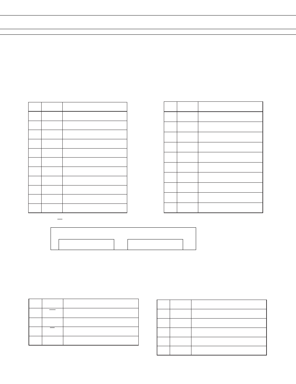
CONNECTOR PIN ASSIGNMENT FOR PRINTER MECHANISM
1. Thermal Head
Head side 1 : B11B-PH-K-S-2.2 (J.S.T.) or equivalent
2: B10B-PH-K-S-2.2 (J.S.T.) or equivalent
Board side 1: PHR-11 (J.S.T.) or equivalent
2: PHR-12 (J.S.T.) or equivalent
*1: Symbol: "
" means a negative logic signal
Motor
Thermal head heat sink
Head up level
Connector Pin No.
3. Sensor connectors
Sensor : PHR-5 (J.S.T.) or equivalent
Board side : B5B-PH-K-S (J.S.T.) or equivalent
.
o
N
l
a
n
g
i
S
t
n
e
m
m
o
C
1
N
E
S
V
r
o
s
n
e
s
r
e
p
a
p
r
o
f
r
e
w
o
P
2
E
H
P
r
o
t
t
i
m
e
r
e
t
p
u
r
r
e
t
n
i
o
t
o
h
P
3
K
H
P
e
d
o
h
t
a
c
r
e
t
p
u
r
r
e
t
n
i
o
t
o
h
P
4
1
W
S
1
h
c
t
i
w
s
t
c
e
t
e
d
p
u
d
a
e
H
5
2
W
S
2
h
c
t
i
w
s
t
c
e
t
e
d
p
u
d
a
e
H
.
o
N
l
a
n
g
i
S
t
n
e
m
m
o
C
1
B
n
o
i
t
a
t
i
c
x
e
li
o
c
r
o
t
o
m
g
n
i
p
p
e
t
S
2
B
n
o
i
t
a
t
i
c
x
e
li
o
c
r
o
t
o
m
g
n
i
p
p
e
t
S
3
A
n
o
i
t
a
t
i
c
x
e
li
o
c
r
o
t
o
m
g
n
i
p
p
e
t
S
4
A
n
o
i
t
a
t
i
c
x
e
li
o
c
r
o
t
o
m
g
n
i
p
p
e
t
S
.
o
N
l
a
n
g
i
S
t
n
e
m
m
o
C
1
H
V
d
a
e
h
r
o
f
r
e
w
o
P
2
H
V
d
a
e
h
r
o
f
r
e
w
o
P
3
D
N
G
d
n
u
o
r
g
d
a
e
H
4
D
N
G
d
n
u
o
r
g
d
a
e
H
5
*
H
T
1
n
o
i
t
c
e
t
e
d
e
r
u
t
a
r
e
p
m
e
T
6
1
B
T
S
1
l
a
n
g
i
s
e
l
b
a
n
e
t
n
i
r
P
7
2
B
T
S
2
l
a
n
g
i
s
e
l
b
a
n
e
t
n
i
r
P
8
3
B
T
S
3
l
a
n
g
i
s
e
l
b
a
n
e
t
n
i
r
P
9
4
B
T
S
4
l
a
n
g
i
s
e
l
b
a
n
e
t
n
i
r
P
0
1
D
D
V
c
i
g
o
l
r
o
f
r
e
w
o
P
.
o
N
l
a
n
g
i
S
t
n
e
m
m
o
C
1
5
B
T
S
5
l
a
n
g
i
s
e
l
b
a
n
e
t
n
i
r
P
2
6
B
T
S
6
l
a
n
g
i
s
e
l
b
a
n
e
t
n
i
r
P
3
7
B
T
S
7
l
a
n
g
i
s
e
l
b
a
n
e
t
n
i
r
P
4
8
B
T
S
8
l
a
n
g
i
s
e
l
b
a
n
e
t
n
i
r
P
5
K
L
C
k
c
o
l
c
n
o
i
s
s
i
m
s
n
a
r
t
a
t
a
D
6
T
A
L
l
a
n
g
i
s
g
n
i
h
c
t
a
l
a
t
a
d
t
n
i
r
P
7
N
I
D
l
a
n
g
i
s
t
u
p
t
u
o
a
t
a
d
t
n
i
r
P
8
D
N
G
d
n
u
o
r
g
d
a
e
H
9
D
N
G
d
n
u
o
r
g
d
a
e
H
0
1
H
V
d
a
e
h
r
o
f
r
e
w
o
P
1
1
H
V
d
a
e
h
r
o
f
r
e
w
o
P
Connector Thermal Head 1
Connector Thermal Head 2
1, 2, 3, ...............9, 10
1, 2, 3, ...............10, 11