Momentary mode, Multiple units – Furman Sound PS-PRO HT User Manual
Page 8
P S - P R O H T - P O W E R CO N D I T I O N E R / S E Q U E N C E R
The front-panel key lock switch is not the primary
means of control in the momentary mode and
should normally be left in REM. It may be a useful
secondary means of control in the rare case of
having several PS-PRO HT’s in parallel if there
is some reason to shut down one unit without
affecting the others.
Because it is a maintained-contact switch, the
RS-1 is not an appropriate remote switch for
the PS-PRO HT when it is in momentary mode.
The Furman RS-2 is the proper choice. Please
contact Furman for RS-2 wiring diagrams.
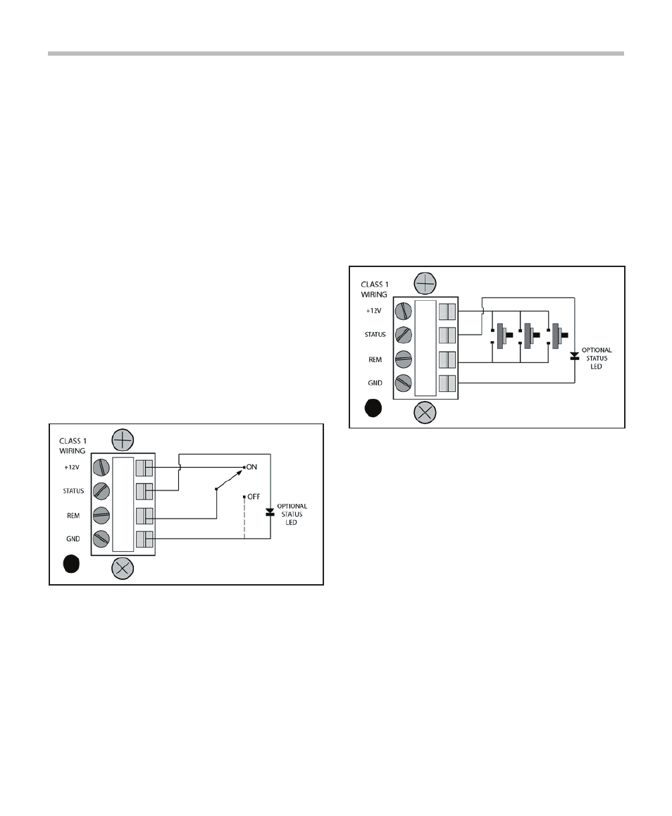
Multiple Units
You can use more than one PS-PRO HT to
handle loads that exceed 20 amps. To control
them remotely with one or more remote switches,
connect the REM to REM, +12V to +12V, GND to
GND terminals of all units together. Be sure
that the mode (momentary or maintained) of all
units is set the same. Set all key lock switches
to REM. Connect a single maintained switch or
one or more momentary switches to the nearest
PS-PRO HT, as discussed in the sections above.
To avoid tripping house breakers, the power
input for each PS-PRO HT should come from a
separate 20 amp AC circuit. If you are unsure
whether your building’s wiring can accommodate
multiple fully-loaded PS-PRO HTs consult a
qualified electrician.
If multiple PS-PRO HTs are controlled by one
or more momentary remote switches, all of the
PS-PRO HTs will change state (from on to off or
vice versa) on each rising edge of the voltage on
the REM IN terminal. The key lock switches on
each unit’s front panel will turn off an individual
unit that is currently on without affecting the
The connection of the REM terminal to the GND
terminal initiates an ON sequence. Disconnecting
initiates an OFF sequence.
Momentary Mode
In Momentary Mode
(jumper plug installed on
JMP2) the PS-PRO HT has “memory” — it only
needs a momentary signal from the remote switch
to change its state from ON to OFF. When first
plugged in (or after power is lost and reapplied for
any reason) the stored state is OFF. The unit will
stay off until sequenced ON by a momentary
connection of the REM IN terminal to +12V (the
key switch must be in the REM position). The
sequence
starts on the rising edge of the signal.
One or more remote momentary switches that
may be connected to the terminal strip in the
rear.
The “memory” is independent of the key switch.
This means that even if the unit is sequenced off
by turning the key lock switch to OFF, when the
key lock switch is turned back to REM, the unit
will sequence back on. The unit “remembers” its
state until the incoming power is lost, in which
case it would default back to OFF.
7