Front panel – Furman Sound PS-PRO HT User Manual
Page 6
P S - P R O H T - P O W E R CO N D I T I O N E R / S E Q U E N C E R
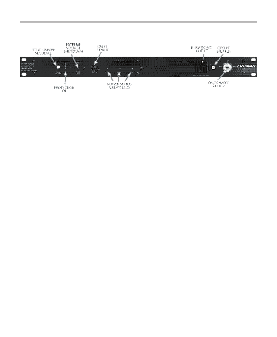
START ON/OFF SEQUENCE: This pushbutton switch
is used only when the key lock switch is in REM posi-
tion and the PS-PRO HT is in Momentary Mode. It
then acts the same as any other remote momentary
switch that may be connected to the rear panel ter-
minal strip. If the switched outlets are on, pushing
it begins an OFF sequence. If they are off , pushing
it begins an ON sequence. Do not use this switch
when in Maintained Mode.
PROTECTION OK: This LED is normally on when the
power to the PS-PRO HT’s outlets is switched on.
It monitors the integrity of the protection devices
and reports if the protection is compromised. If an
extremely large spike is encountered that exceeds
the PS-PRO HT’s capacity, the main group of input
protectors will blow an internal fuse, causing the
indicator to go out. If this LED is not lit when the
power switch is on, full protection is not function-
ing. Spike protection may still exist, but will have
a reduced capacity to absorb current. If this LED is
not lit, please contact the Furman Service Depart-
ment.
EXTREME VOLTAGE SHUTDOWN: This LED indica-
tor is normally off . It monitors a hazard common
in the entertainment industry—wiring faults—for
example, accidental connection to 220V. The PS-
PRO HT senses voltages that are so high or low
that operation would be impossible (under 80V
or over 140V) and shuts the power down before
damage can occur. Upon initially applying power
to the PS-PRO HT, this indicator will be lit if the
unit is receiving below 80 volts or more than 140
volts, and power will not be applied to the PS-PRO
HT’s outlets. If the unit has been operating with
an acceptable input voltage and then the voltage
goes out of the acceptable range, the PS-PRO HT
will shut down power to all of its switched outlets
simultaneously, without observing the OFF delay
cycle, and this LED will begin fl ashing. When power
returns to within the acceptable range, the PS-PRO
HT will observe its ON delays as it returns power to
its switched outlets, and this LED will go out.
NOTE: If the mains power is below 80 volts and
has caused the PS-PRO HT to remove power from
its outlets, the PS-PRO HT will not restore power
to its outlets until the mains voltage is more than
90 volts. If the mains power is above 140 volts and
has caused the PS-PRO HT to remove power from
its outlets, the PS-PRO HT will not restore power to
its outlets until the mains voltage is less than 130
volts. The reason for this is to prevent the power
oscillating on and off in marginal conditions.
DELAY ADJUST: This screwdriver-adjustable trimpot
allows you to set the total turn-on/turn-off delay
time from 1 to 60 seconds, as explained on page 4.
The trimpot adjusts both the on delay and off delay
times simultaneously. Turn the trimpot clockwise to
increase the on and off delay times; turn the trimpot
counterclockwise to decrease the delay times.
POWER STATUS (DELAY) LEDs: One green LED is pro-
vided for each of the three delay stages. Each LED
lights when power is applied to its corresponding
duplex outlet on the rear panel. All three LEDs then
remain steadily lit until power is removed. During
the power-down delay cycle, each LED goes off as
power to its corresponding outlet is removed. In
addition, the Delay 1 LED fl ashes if a remote switch
(or the stored state) is OFF.
UNSWITCHED OUTLET: This convenient outlet
provides power at all times when the PS-PRO HT
is plugged in and operating under normal power
conditions.
ON/REM/OFF SWITCH: When turned to the ON posi-
tion, this key lock switch initiates an ON sequence,
applying power to the PS-PRO HT’s switched out-
lets. When turned to the OFF position, it begins an
5
FRONT PANEL