FUJITSU MHV2060BH User Manual
Page 140
Interface
5-64
C141-E224
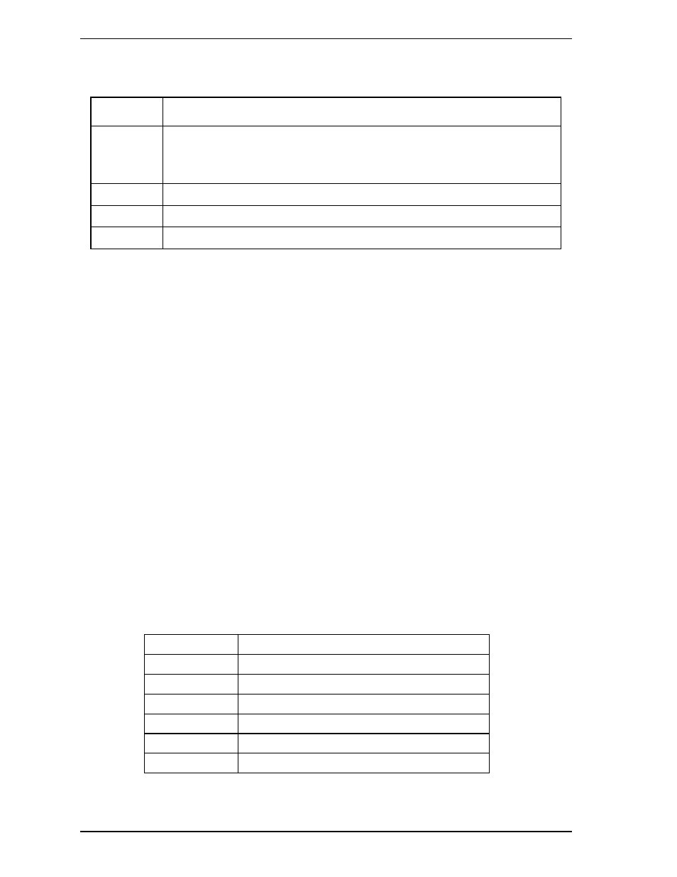
Table 5.19 Data format of SMART Summary Error Log (2/2)
Byte Item
5C to 1C3
Error log data structure 2
to
Error log data structure 5
1C4, 1C5
Total number of drive errors
1C6 to 1FE Reserved
1FF Check
sum
• Command data structure
Indicates the command received when an error occurs.
• Error data structure
Indicates the status register when an error occurs.
• Total number of drive errors
Indicates total number of errors registered in the error log.
• Checksum
Two's complement of the lower byte, obtained by adding 511-byte data one byte at a
time from the beginning.
• Status
Bits 0 to 3: Indicates the drive status when received error commands according
to the following table.
Bits 4 to 7: Vendor unique
Status Meaning
0 Unclear
status
1 Sleep
status
2 Standby
status
3
Active status (BSY bit = 0)
4
Off-line data collection being executed
5 to F
Reserved