Wiring – Furuno IF-NMEASC User Manual
Page 10
2
2.
WIRING
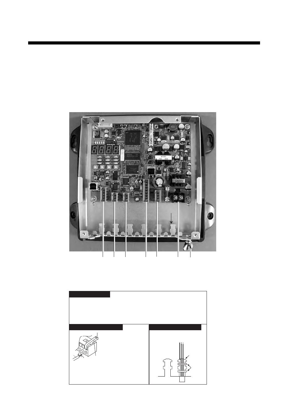
Open the IF unit with your hands, detach the shield cover and connect external equipment, refer-
ring to the illustration below and the interconnection diagram. Cables are mainly connected to the
unit with WAGO connectors. See the instructions below for how to attach wiring to the connectors.
The opener for the WAGO connectors is attached to the inside of the inner cover. Fix cables to
their respective cable posts with cable ties (supplied). Run a ground wire (IV-2.0sq., local supply)
between the ground terminal and ship's grounding bus. Supply power from breaker on mains
switchboard.
Power cable
J8 (Analog)
J7 (SC-30 Sensor)
J5 (NMEA 0183)
J4 (NMEA 0183)
J3 (AD-10)
Ground terminal
Power cable:
AWG 16-20, and diameter less than 10 mm
(JIS* cable DPYC-1.5 or equivalent)
All other cables: AWG 16-28, shield, twisted, and diameter less than 8 mm
(JIS* cable TTYCS-1, TTYCS-4 or equivalent)
Cable
post
Fix cable to cable post with
two cable ties (supplied).
Cable tie
Cable post
Recommended Cables
How to wire WAGO connector
How to fix cable to cable post
1. Insert opener.
2. Press opener.
3. Insert core.
4. Release opener
.
Opener
Wire
Twist
* Japan Industry Standard cable