Wiring, 1 connections, W i ring – Furuno 1712 User Manual
Page 13: Connection of external equipment
7
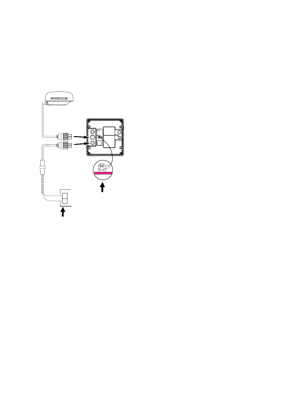
2. WIRING
2.1 Connections
Connect the antenna cable, the power cable
and the ground wire as shown in Figure 13.
FUSE (5A)
DISPLAY UNIT
GROUND
Connect ground
wire to bolt fastened
(or welded) to hull.
ANTENNA UNIT
: Antenna of MODEL 1622,
1621 or 1621M2 is available.
WHT (+)
BLK (-)
POWER SUPPLY
12/24 VDC
+
-
Signal cable
(select one)
MJ-A10SPF0009-050 (5m)
MJ-A10SPF0009-100 (10m)
MJ-A10SPF0009-150 (15m)
MJ-A10SPF0009-200 (20m)
MJ-A10SPF0009-300 (30m)
P
o
wer cab
le
MJ-A3SPF0019-035 (3.5m)
*
1
*
2
*
1
*
2
: Optional for 24 VDC ship's
mains only.
Figure 13 Connections
Connection of external
equipment
Navigator/echosounder
This radar can receive the following NMEA
0183 format data sentences from a navigator or
echosounder:
GLL:
Geographic position - Lat/Long
BWR:
Bearing and Distance to Waypoint -
Rhumb line
BWC:
Bearing and Distance to Waypoint
GLC:
Geographic Position - Loran-C
GTD:
Geographic Position - Time Difference
RMA: Recommended
Minimum
Specific
Loran-C Data
RMB:
Recommended Minimum Navigation
Information
RMC: Recommended
Minimum
Specific
GPS/Transit Data
VTG:
Track Made Good and Ground Speed
MTW: Water
Temperature
DBT:
Depth Below Transducer
DBS:
Depth Below Surface
DPT:
Depth Below Transducer with offset
value
GGA:
GPS - Rx status, L/L