FUJITSU SRS-9924-ABM User Manual
Page 67
4-3
4
Using the
NI
/
5E Custom
SRS-9924-ABM
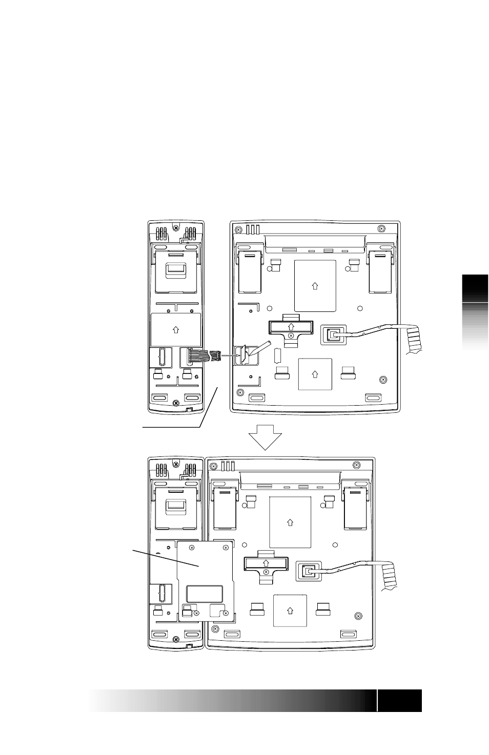
The module attaches on the right side of the terminal as shown in Figure 4-
2.
To attach the ABM:
1. Use a sharp object, remove the cover from the ABM jack on the bottom
of the terminal, then plug in the ABM cable.
2. Place the ABM and the terminal side-by-side to position the connector
plate.
3. Insert and tighten the four screws to connect the two units.
Figure 4-3: SRS-9924-ABM Bottom View
Cable
Connector
Plate