Mounting platform, Wiring and final preparation, Figure 5-4 antenna unit, cover removed – Furuno 841 MARK-2 User Manual
Page 42: Figure 5-6 antenna unit, inside view
30
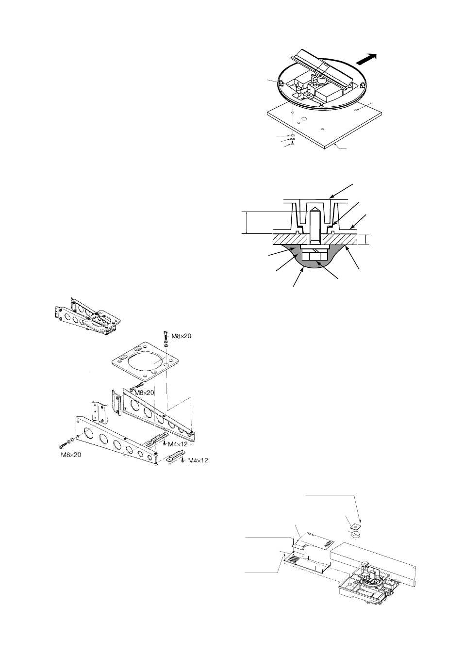
Mounting platform
Holes for antenna unit:
The mounting surface must be parallel with
the waterline and provided with five holes
whose dimensions are shown in the outline
drawing attached at the end of this manual.
The unit is adjusted so a target echo returned
from the bow direction will be shown on the
zero degree (heading line) position on the
screen. When drilling holes, be sure they are
parallel with the fore and aft line.
3. Prepare a platform of 5 to 10 millimeters in
thickness for the antenna unit. (A mounting
bracket for mounting the antenna unit on a
sailboat mast is optionally available. See Fig-
ure 5-1.) Find the cable entry on the radome
base. Next, position the radome base so the
cable entry faces the stern direction. This
alignment must be as accurate as possible.
Fasten the radome base to the mounting plat-
form with four each of M10 x 25 hex bolts,
flat washers and spring washers.
Type: OP03-92
Code no.: 008-445-070
Figure 5-3 Assembling the sailboat mast
mounting bracket (option)
FLAT WASHER
SPRING WASHER
M10 x 25 HEX BOLT
PLATFORM
4-
φ
12 HOLES
CABLE
ENTRY
SHIP'S BOW
Figure 5-4 Antenna Unit, cover removed
Flat
washer
Spring
washer
Platform
Antenna base plate
M10 x 25
Hex bolt
Radome
5 - 10 mm
Apply silicone sealant
Effective
thread length
25 mm
Packing
Figure 5-5 How to fasten the radome base
to the mounting platform
Wiring and final preparation
4. Drill a hole of at least 20 millimeters diam-
eter through the deck or bulkhead to run the
signal cable between the antenna unit and
the display unit. (To prevent electrical inter-
ference avoid running the signal cable near
other electrical equipment and in parallel
with power cables.) Pass the cable through
the hole. Then, seal the hole with sealing
compound for waterproofing.
5. Remove two shield covers in the radome.
6. Remove the cable clamping plate by unfas-
tening four screws and removing a gasket.
Shield cover
Shield cover
Pan head
screws
M4x8 7 pcs.
Pan head
screws
M4x8 7 pcs.
Pan head screws
M4x8 4 pcs.
Gasket
Cable clamping plate
Figure 5-6 Antenna unit, inside view
Mask size;
φ
70 to
φ
125 mm