Pc interface cable – Fluke DSP-2000 User Manual
Page 151
Maintenance and Specifications
Specifications
8
8-13
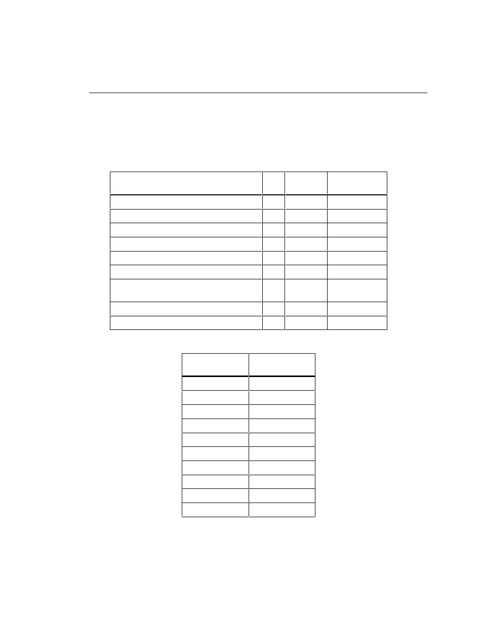
PC Interface Cable
Table 8-7 shows the pin connections for the PC interface cable provided with the
test tool. Table 8-8 shows the pin connections for the 9-to 25-pin adapter available
from Fluke (part number 929187).
Table 8-7. PC Interface Cable Connections
Test Tool End
DB9S (female)
Pin
Direction
PC End
DB9S (female)
Data Carrier Detect
1
<-----
4
Receive Data
2
<-----
3
Transmit Data
3
----->
2
Data Terminal Ready (always true)
4
----->
1
Signal Ground
5
<---->
5
Not connected
6
6
Request To Send (used only with hardware
flow control)
7
----->
8
Clear To Send
8
<-----
7
Not connected
9
9
Table 8-8. 9-to 25-pin Adapter (available from Fluke)
9-pin Connector
25-pin
Connector
3
2
2
3
7
4
8
5
6
6
5
7
1
8
4
20
9
22
Shell
Shell
This manual is related to the following products: