9500 valve, Instruction manual – Fisher 9500 User Manual
Page 14
9500 Valve
Instruction Manual
Form 2433
November 2007
14
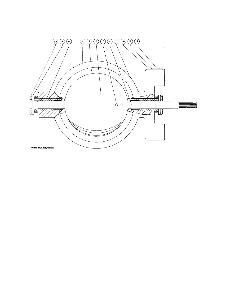
Figure 7. Type 9500 Valve Body Assembly
G34171-B/DOC
Key
Description
Part Number
15*
Taper Pin (2 req’d) (continued)
S17400 (17-4 PH)
NPS 2
F1368135362
NPS 3
G1194435362
NPS 4
G1194235362
NPS 6
G1194035362
NPS 8
G1193835362
NPS 10
G1329135362
NPS 12
H1374835362
S20910
NPS 2
F13681K0022
NPS 3
G11944K0032
NPS 4
G11942K0012
NPS 6
G11940K0022
Key
Description
Part Number
15*
Taper Pin (2 req’d) (continued)
S20910
NPS 8
G11938K0032
NPS 10
G13291K0012
NPS 12
H13748K0032
16
Nameplate
17
Drive Screw, steel (2 req’d)
19
Flow Tag, stainless steel (Fishtail disc only)
21
Fishtail Disc Tag (Fishtail disc only)
22
Flange Tag (not shown)
26
Seal & Wire (not shown)
130
Clamp, stainless steel
131
Bounding strap assembly
132
Flange Adapter (not shown) (2 req’d)
*Recommended spare parts