Expansion cards, Expansion card installation procedure, 1 expansion card installation procedure – FUJITSU D1241 User Manual
Page 24: 7 expansion cards, Hardware setup, Peer-to-peer pci bus configuration diagram, 20 user’s manual
20
User’s Manual
3. HARDWARE SETUP
3.7 Expansion Cards
WARNING!
Unplug your power supply when adding or removing expansion
cards or other system components. Failure to do so may cause severe damage to
both your motherboard and expansion cards.
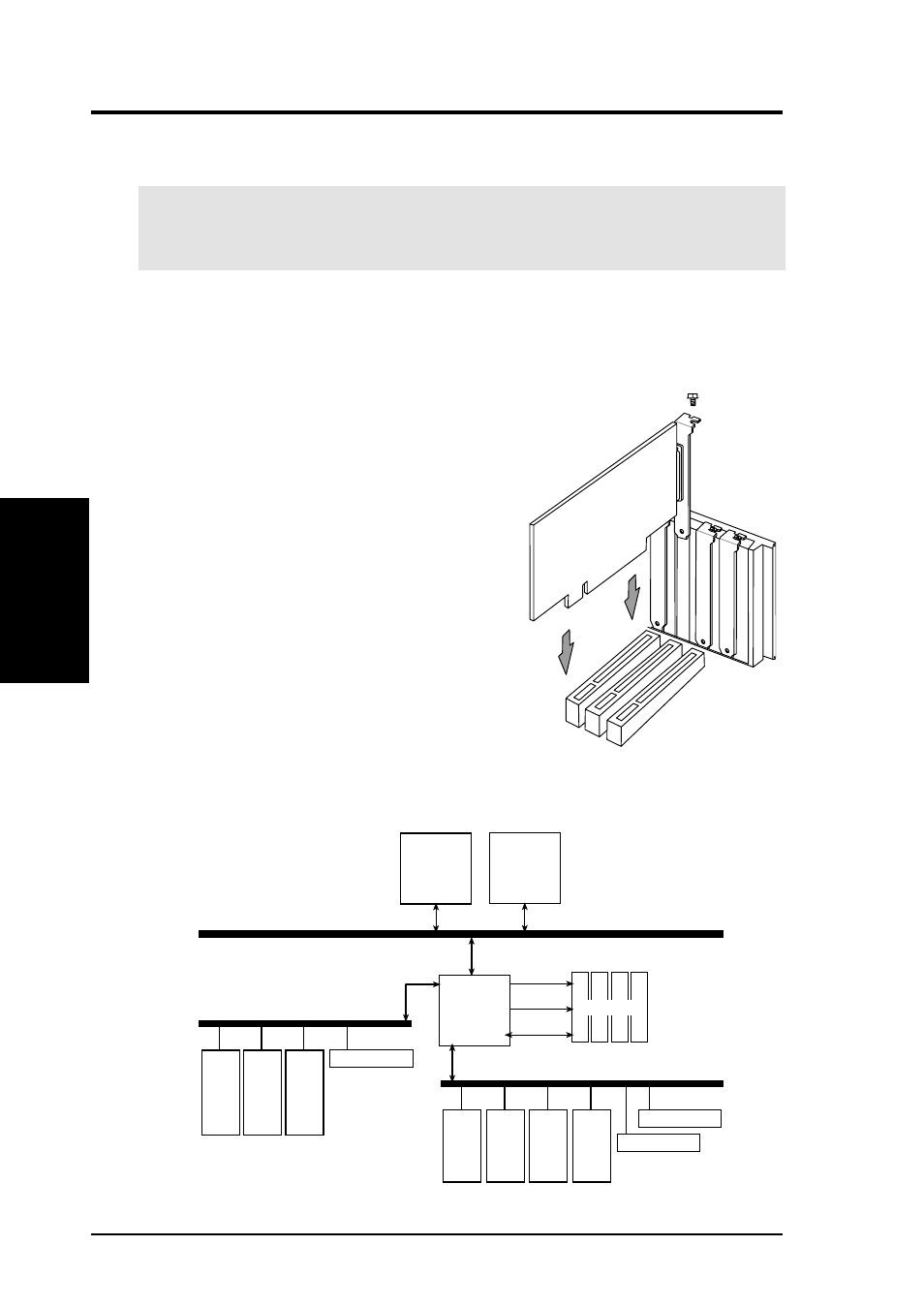
3.7.1 Expansion Card Installation Procedure
1. Read the documentation for your expansion card and make any necessary hard-
ware or software settings for your expansion card, such as jumpers.
2. Remove your computer system’s cover and the
bracket plate on the slot you intend to use.
Keep the bracket for possible future use.
3. Carefully align the card’s connectors and press
firmly.
4. Secure the card on the slot with the screw you
removed above.
5. Replace the computer system’s cover.
6. Set up the BIOS if necessary
(see 4.4.3 PCI Configuration)
7. Install the necessary software drivers for your
expansion card.
Expansion Cards
3. H/W SETUP
Socket 370
Socket 370
RCC
CNB30LE
MA
Cntl
MD
100/133MHz
Buffer DIMM
Peer-to-Peer PCI Bus
Configuration Diagram
PCI-5
64-bit
PCI-6
64-bit
PCI-7
32-bit
LSI SCSI
Secondary PCI Bus (66/33MHz)
PCI-1
32-bit
PCI-2
32-bit
PCI-3
32-bit
ATI RageXL
Primary PCI Bus (33MHz)
PCI-4
32-bit
Intel 82559
<53C1010-66
<53C1010-33
<896
33MHz
33MHz
33MHz
33MHz
33MHz
33MHz
(none)
66MHz
66MHz
Peer-to-Peer PCI Bus Configuration Diagram