Dimm installation, 2 dimm installation, Hardware setup – FUJITSU D1241 User Manual
Page 22
18
User’s Manual
3. HARDWARE SETUP
System Memory
3. H/W SETUP
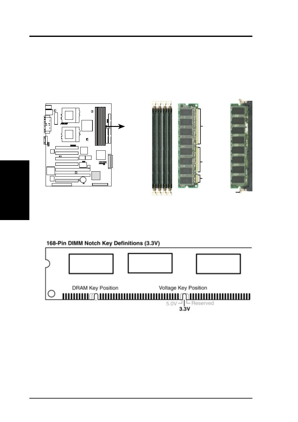
3.5.2 DIMM Installation
Insert the module(s) as shown. Because the number of pins are different on either
side of the breaks, the module will only fit in the orientation shown. DIMMs are
longer and have different pin contacts on each side and therefore have a higher pin
density compared to SIMMs.
CUR-DLS 168-Pin DIMM Sockets
20 Pins
60 Pins
88 Pins
Lock
CUR-DLS
R
The DIMMs must be 3.3V “registered” for this motherboard. To determine the DIMM
type, check the notches on the DIMMs (see figure below).
The notches on the DIMM module will shift between left, center, or right to identify
the type and also to prevent the wrong type from being inserted into the DIMM slot
on the motherboard. You must ask your retailer the correct DIMM type before pur-
chasing.
- XG Series P3NK-4452-01ENZD (614 pages)
- FPCAC14C (1 page)
- MCJ3230SS (161 pages)
- MBA3073NC (138 pages)
- T5140 (102 pages)
- T5140 (76 pages)
- MAM3367MC/MP (152 pages)
- MPC3045AH (185 pages)
- MB2142-02 (23 pages)
- MB15F86UL (6 pages)
- MHS2030AT (40 pages)
- MHW2100BS (296 pages)
- MHK2060AT (227 pages)
- Disk Drives MHK2060AT (227 pages)
- MCM3064SS (170 pages)
- Mainboard D1561 (45 pages)
- MHC2040AT (219 pages)
- D1961 (45 pages)
- DISK DRIVES MHM2100AT (231 pages)
- MHR2010AT (250 pages)
- MHZ2120BJ (320 pages)
- MCE3064AP (175 pages)
- LQFP-64P (16 pages)
- Solaris PCI GigabitEthernet 3.0 (115 pages)
- MAY2036RC (94 pages)
- MAB3091 (142 pages)
- MPE3XXXAT (191 pages)
- MHV2040AH (40 pages)
- MHW2040AC (278 pages)
- ETERNUSmgr P2X0-0202-01EN (64 pages)
- VSS Hardware Provider 2.1 (134 pages)
- MAG3182FC (61 pages)
- MAU3147NC/NP (130 pages)
- MAX3147RC (94 pages)
- MHV2160BT (296 pages)
- MHV2040AT (280 pages)
- MAW3300NC/NP (130 pages)
- DeskPower E623 (50 pages)
- MAG3182LC (133 pages)
- OPTICAL DISK DRIVES MDG3064UB (42 pages)
- MHF2021AT (225 pages)
- MHR2040AT (40 pages)
- Single Drive FTM7926FB (1 page)
- PG-FCS103 (98 pages)
- MAS3735FC (114 pages)