Rear panel 7 – Fender Acoustasonic Ultralight User Manual
Page 7
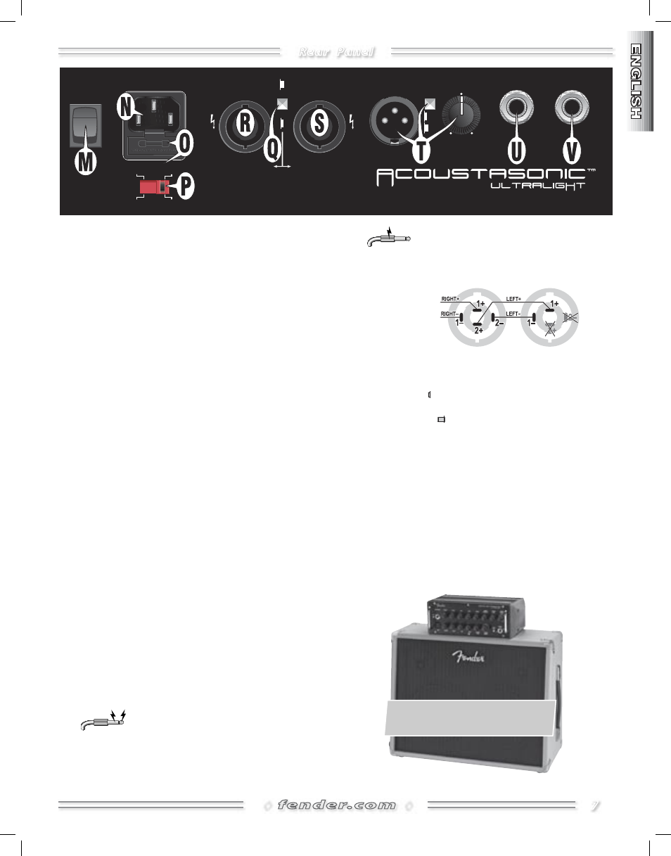
Rear Panel
7
◊
◊
�����
����
����
������
������
����
�����
��
��������
�����
���
���
���
����
��
��
��
���
��
��
��
���
INPUT POWER
500W
FUSE
�����
����
���
����
���������
����
���������
�������
����������
���������
������
����
2 CONDUCTOR = LEFT
2 CONDUCTOR = MONO
2 CONDUCTOR = MONO
4 CONDUCTOR = STEREO R/L
2 CONDUCTOR = RIGHT
12
0
��
M. POWER— Switches the unit ON-OFF.
N. IEC POWER INPUT SOCKET— Connect to a grounded
outlet in accordance with the correct Voltage Selector {P}
setting for your location. When you travel outside your
country, make sure you have a power cord compatible
with each destination.
O. FUSE— Protects the amplifier from electrical faults. Only
replace a blown fuse with the type and rating specified
for the correct Voltage Selector {P} setting. Install the cor-
rect fuse when you change the Voltage Selector setting
and before connecting the power cord. To replace the
fuse, first remove the power cord, then use a screwdriver
to pry the fuse holder out from the input socket.
P. VOLTAGE SELECTOR— Set according to the local power
supply before connecting the power cord.
Q. STEREO/MONO MODE— Selects the mode of operation
for your Acoustasonic Ultralight amplifier. Turn the unit
OFF before switching modes and change speaker con-
nections before turning the unit back ON.
R/S. RIGHT & LEFT SPEAKER OUTPUTS — Connect one of the
following speaker configurations:
• An Acoustasonic Ultralight Stereo Enclosure—set the
mode switch {Q} to Stereo, then connect the speaker
to the Right {R} output using the supplied 4-conductor
Speakon® cable. NOTE: Do NOT use the Left {S} output
with this setup to avoid overloading the unit.
• Right/Left channel speakers, each 4-ohms minimum—
connect to Right {R} and Left {S} outputs using 2–conduc-
tor cables, each with a Speakon® plug on one end and a
plug matching the speaker input on the other end.
• Right/Left channel speakers, each 4-ohms minimum—
connect BOTH speakers to the Right {R} output using a
cable (adapter) that has a 4-conductor Speakon® plug on
one end and two, 2-conductor plugs matching the speaker
inputs on the other end. NOTE: Do NOT use the Left {S}
output with this setup to avoid overloading the unit.
CAUTION: Speaker outputs have 20 volts
present on BOTH conductors and the ampli-
fier will shut down if either one comes into contact with a
grounded surface.
Any exposed metal on plug jackets must
not touch ground when speaker cables are
connected; use insulated (plastic) plug jackets whenever
possible.
SPEAKER
OUTPUT
DIAGRAM
T. LINE OUTPUT— Balanced XLR output for connection to
sound equipment.
• Ground Lift:
Press IN to disconnect the ground con-
nection (pin 1) which may reduce noise caused by non-
standard wiring. Normally leave Ground Lift OUT.
• Line Out Level: Adjusts signal strength to accommodate
the input sensitivity of external equipment.
U. FOOTSWITCH— Plug the included footswitch to enable
remote effects on-off switching for each channel, as
indicated by the footswitch LEDs. Connect the footswitch
using an unshielded speaker cable rather than an instru-
ment cable whenever possible.
V. TUNER OUT— Connect your tuner here. Press Tuner/
Mute {J} on the front panel for silent tuning.
Recommended Enclosure: The Fender®
Acoustasonic™ Ultralight Stereo Enclosure
(Part Number: 227-1700-000)
�����
����