Name of parts, En-2, Electrical breaker – FUJITSU AOU36RC User Manual
Page 3
En-2
°F
NON STOP
AMPM CLOCK
AMPM TIMER
NEXT DAY
DAY
OFFON
TIMER
WEEKLY
AUTO
OFF
ON
OFF
ON
DAY OFF
DEFROST TEST
2
1
AUTO
HEAT
FAN
COOL
TIMER
MODE
SET
ZONE
START/STOP
CLOCK ADJUST
SET TIME
TEMP./DAY
FAN
CONTROL
MASTER
CONTROL
DAY OFF
ENERGY SAVE
°F
NON STOP
AM
CLOCK
AUTO
F
E
D
C
0
A
7
9
B
8 6
I
H
L
G
J
K
M
N
O
P
Q R
S T
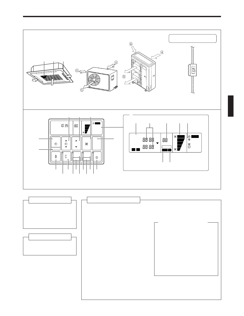
NAME OF PARTS
Fig. 1
Fig. 2
This breaker is installed during
the electrical installation.
Electrical Breaker
Fig. 3
Fig. 4
●
For explanatory purposes, the figure showing the remote
controller display shows all possible displays. The actual
display shows only that area that is being adjusted or used.
Fig. 5 Display
Fig. 1 Indoor Unit
1 Air Filter
2 Air Intake Grille
3 Air Flow Direction
Flaps
Fig. 2 Outdoor Unit
4 Air intake
5 Air outlet
Fig. 4 Remote Controller
6 START/STOP Button
7 Operation Lamp
8 ENERGY SAVE Button
9 DAY OFF Button
0 ENERGY SAVE Lamp
A ZONE Control Button
B SET Button
C ZONE Control Lamp
D AIR FLOW DIRECTION SWING
Button
E AIR FLOW DIRECTION SWING
Lamp
F AIR FLOW DIRECTION SET Button
G CLOCK ADJUST Button
H TIMER MODE Button
I SET TIME Button
J TEMP./DAY Button
M Remote Controller Display
(Fig. 5)
N Timer Mode Display
O Clock Display (CLOCK/TIMER)
P Set Temperature Display
(TEMP.)
Q Fan Speed Display
R Operation Mode Display
S DEFROST Display
T TEST Display
Instructions relating to heating (*) are applicable only to “HEAT & COOL MODEL” (Reverse Cycle).
K FAN CONTROL Button
L MASTER CONTROL Button
1
3
2